
What an ODM Rapid Prototyping Solution Actually Has to Deliver
An ODM rapid prototyping solution is not just machining to a CAD file. This page breaks down where the value sits: DFM feedback before cutting starts, tolerance choices that match function, in-house finishing, and low-volume bridge runs. Written for design and manufacturing engineers who have to pick a partner and defend the choice.
In this article
- 1
- 2
- 3
- 4
- 5
- 6
What separates ODM prototyping from plain build-to-print
Build-to-print means you send a model, the shop machines it, and the drawing is treated as final. An ODM rapid prototyping solution works differently. The supplier reads your design intent, questions wall thickness, undercuts, datum choices, and surface callouts before the first tool is loaded. That early read is the product. Without it you are paying for spindle time and discovering the same problems your own team already missed.
The practical test is simple. Send a model, a 1-page intent note, and a target build quantity. A real ODM partner comes back with a DFM sheet inside 12 hours: flagged features, suggested tolerances per face, a material alternative if yours is on allocation, and a rough cost driver list. A vendor shop comes back with a price and a delivery date. Both answers look similar on the surface. They are not.
ODM also implies continuity. The same partner should be able to take the approved prototype into a small bridge run, then into die casting or vacuum casting if volumes climb. When the prototype shop and the production shop are different companies, you re-qualify the part twice, and the second shop usually finds the tolerance stack-up the first one hid.
- 1DFM before cuttingWritten feedback on features, datums, and tolerances, not a verbal note.
- 2One finish chainAnodizing, plating, and laser marking happen under the same roof.
- 3Bridge to volumeThe prototype supplier can carry the part into low-volume production.
- 4Confidentiality from day oneNDA available on request; uploads handled as secure and confidential.
How ODM rapid prototyping solution work gets sequenced
Most projects move through four stages: geometry review, material and process selection, precision machining, and finishing plus inspection. Each stage has a decision that locks in cost. Get geometry wrong and you pay for a redesign. Get material wrong and you pay for a surface finish that never sticks. Get precision wrong and the assembly does not close.
Geometry review is where the money is saved. A 5-axis setup can reach a compound angle in one fixturing, while a 3-axis setup needs two or three. That does not mean 5-axis is always correct. For a simple plate with through holes, a 3-axis machine holds ±0.005 mm with less setup risk and lower hourly cost. The engineering answer depends on feature access, not on machine prestige.
Material selection follows function. Aluminium 6061-T6 is the default for housings and brackets because it machines fast and anodizes predictably. 7075 gives higher strength for stressed airframe or robotics links but costs more and welds poorly. Titanium TC4 (Ti-6Al-4V) suits medical and aerospace parts that need high strength-to-weight, but it cuts slowly and tool wear is real. Choosing it for a cosmetic cover is a waste of budget.
Finishing and inspection close the loop. Anodizing changes dimensions slightly, and hardcoat changes them more. If a bore has a ±0.01 mm fit, mask it or finish before the final cut. Inspection is 100% before shipment, with raw material checks, in-process monitoring, and final reports available on request. Ask for the report format early, because some customers need dimensional data per drawing balloon, not a single pass/fail sheet.
- 1Stage 1Geometry and DFM review before any material is cut.
- 2Stage 2Material and process selection against function and budget.
- 3Stage 3Machining with the smallest setup count that holds the tolerance.
- 4Stage 4Finishing, masking, and 100% inspection before shipment.
Tolerance, surface finish, and what each one costs
A tolerance callout is a cost decision. General machining holds ±0.005 mm on critical features when the setup supports it, but applying that number to every dimension on a part is unnecessary. Bolt clearance holes do not need it. Bearing bores and sealing faces do. The disciplined approach is to tolerance by function and leave the rest at general block tolerance.
Surface finish follows the same logic. As-machined at Ra 1.6–3.2 μm is fine for internal brackets. Ra 0.8–1.6 μm covers most sealing and sliding surfaces. Ra 0.2–0.8 μm is reserved for optical, medical, or high-cycle contact faces, and it usually requires a finishing pass, slower feed, or a secondary polish. Every step down in Ra adds time, and time is the cost.
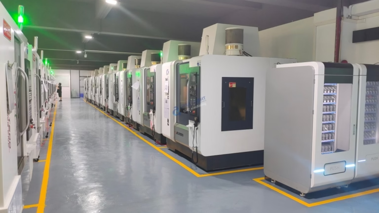
Size matters too. GreatLight runs 127 high-precision CNC machines, including 16 simultaneous 5-axis centers, 12 four-axis mills, 27 three-axis machines, and 16 mill-turn centers. The largest travel is 4,000 × 400 × 150 mm, with medium envelopes at 750 × 1,150 × 550 mm and compact cells at 500 × 500 × 450 mm. A Ø400 mm rotary table handles round work that would otherwise need a second setup.
The engineering meaning is straightforward. Big parts need big machines, and big machines change the fixturing plan. A 4,000 mm frame cannot be repositioned casually mid-run without introducing stack-up error. Plan the datum strategy before the first cut, not after the first out-of-tolerance report.
- 1Tolerance by functionReserve ±0.005 mm for fits, bores, and sealing faces.
- 2Finish by contactRa 0.8–1.6 μm covers most sliding and sealing surfaces.
- 3Size drives setupLarge frames need a datum plan fixed before machining.
Material choices that decide the prototype outcome
Aluminium covers most prototype work. 6061 and 6061-T6 are the workhorses for housings, brackets, and heat sinks. 7075 is for high-stress parts such as robotics arms and airframe fittings. 2024 has better fatigue behavior but poorer corrosion resistance unless it is clad or anodized. ADC12 appears when the prototype is intended to become a die casting, because it matches the production alloy.
Stainless grades 303, 304, 316, and 316L handle medical and food-contact parts, with 316L preferred where corrosion resistance matters most. 17-4PH (SUS630) gives high strength after aging and is common in aerospace and pump components. Tool steel and 4140 appear in molds and fixtures. Titanium TA1, TA2, and TC4 (Ti-6Al-4V) are used where weight and strength cannot be traded off, and Inconel is reserved for high-temperature sections.
Plastics matter for fit checks and cosmetic models. ABS, PC, PMMA, POM, PA, PEEK, PP, HDPE, and carbon fibre all machine differently. POM is dimensionally stable and good for sliding parts. PEEK survives high temperature and chemical exposure but costs significantly more. Carbon fibre gives stiffness at low weight, though dust control and tool wear need attention.
The rule for prototype work is to match the production material whenever the test results must transfer. If the final part is die-cast aluminium, prototyping in a different alloy can hide porosity and shrink behavior. If the final part is molded POM, machining POM is a closer approximation than machining ABS. Material substitution is a valid cost move, but it should be a conscious one.
- 1Aluminium 6061-T6Default for housings, brackets, and heat sinks.
- 217-4PH stainlessHigh strength after aging for aerospace and pump parts.
- 3TC4 titaniumHigh strength-to-weight, slower to cut, higher tool wear.
- 4Match the production alloyKeeps test results transferable to the final process.
When an ODM rapid prototyping solution is the wrong call
Not every project benefits from outsourcing. If your team has in-house 3-axis capacity and the part is a simple bracket with loose tolerances, sending it out adds a shipping cycle and a communication layer for little gain. Keep it in-house and reserve the ODM partner for the parts that need 5-axis access, tight fits, or a finish chain you do not own.
Outsourcing also struggles when the design is still in flux. If the CAD model changes daily, you will pay for setup changes and rework. Freeze the geometry to a revision, accept the DFM notes, then cut. Prototypes built on a moving model produce data that cannot be trusted.
There are cases where the geometry itself is a poor fit for machining. Deep internal channels, hollow lattices, and organic shapes that would need support removal are often better served by 3D printing for the first article, then machined once the design settles. A good partner will say so rather than accept the job.
Finally, consider volume. A prototype supplier with no path to low-volume production will hand you a part that works but cannot scale. If you expect 10,000+ parts, choose a partner who also runs die casting, vacuum casting, or sheet metal fabrication, so the transition does not restart the qualification cycle.
- 1Keep in-houseSimple parts with loose tolerances and available 3-axis capacity.
- 2Freeze the revisionCut only after the model stops changing daily.
- 3Print first, machine laterDeep channels and hollow lattices may need 3D printing first.
Matching the prototype method to the requirement
Pick the row that matches your dominant constraint.
| Requirement | Best fit | Why | Watch out for |
|---|---|---|---|
| Tight metal fits, ±0.005 mm | 5-axis CNC machining | Compound angles in one setup, less stack-up | Higher hourly rate than 3-axis |
| Large frame or long part | CNC up to 4,000 mm | Single-piece travel avoids repositioning error | Datum plan must be fixed early |
| Cosmetic shell, low stiffness need | Vacuum casting or 3D printing | Fast first article, low tooling cost | Not for load-bearing surfaces |
| Production intent is die casting | ADC12 machined prototype | Alloy matches the final process | Machined surface differs from cast skin |
| Medical or food contact | 316L stainless, electropolish | Corrosion resistance and cleanability | Passivation and documentation lead time |
| High-temp or chemical exposure | PEEK or Inconel | Retains properties where others fail | Material cost and slow cutting |
| 10,000+ parts after approval | Partner with casting and sheet metal | No second qualification cycle | Confirm capacity before committing |
The clear trade-off
If your part has tight fits, compound angles, or a required finish chain, choose a full-service ODM partner and pay for the DFM review. If it is a simple bracket with loose tolerances and you own 3-axis capacity, machine it in-house and keep the cycle short.
Questions engineers ask before committing
How fast can an ODM rapid prototyping solution deliver a first article?
Quotation and free DFM analysis come back within 12 hours. Production can start within 24 hours of approval, and parts typically ship in 3–5 days.
Timelines assume the geometry is frozen and the material is in stock. Titanium and Inconel often need a material lead time on top of the machining window.
Do you accept single-piece orders?
Yes. There is no minimum order quantity, from one prototype to 10,000+ part runs.
Single pieces still go through the same DFM review, material check, and 100% inspection as larger runs.
Which certifications apply to prototype work?
GreatLight holds ISO 9001:2015, IATF 16949:2016, ISO 13485:2016, and ISO 27001:2022.
IATF 16949 and ISO 13485 matter when the prototype is a step toward automotive or medical production. ISO 27001 covers information security for customer data.
How do you protect the design during quoting?
Uploads are handled as secure and confidential. An NDA is available on request before files are shared.
The same confidentiality process applies whether the project is a single bracket or a full assembly.
Can the prototype supplier also handle finishing?
Yes. Anodizing in clear, colour, hardcoat, and conductive variants, plus electroless nickel, zinc, silver and gold plating, powder coating, black oxide, bead blasting, tumbling, brushing, polishing, and laser marking.
Laser marking has a minimum character height of 1.5 mm, so plan your label layout accordingly.
What inspection data comes with the parts?
Inspection is 100% before shipment, covering raw material checks, in-process monitoring, and final inspection. Reports are available on request.
Tell the supplier early whether you need ballooned dimensional data or a pass/fail summary, because the report format is set during planning.
Send the model and get a DFM read back
Upload your CAD file and intent note. You get a quote and DFM analysis within 12 hours, with flagged features, suggested tolerances, and a material alternative if needed.
12-hour quoteNo MOQ100% inspectionNDA on request
More from GreatLight
We publish setup notes, tooling trials and inspection data from the factory floor.











