
Collapsible Core Mold Undercut Solution: How It Works
A collapsible core mold undercut solution is the standard way to mold internal threads, snap rings and recesses that block straight ejection. This page explains the mechanism, where it beats unscrewing and side-action tooling, and which part geometries and tolerances decide the choice.
In this article
- 1
- 2
- 3
- 4
- 5
- 6
- 7
Why an Undercut Stops a Straight Pull
An undercut is any molded feature that sits behind a wall of material. A raised thread inside a cap, a snap ring groove, a lip that faces the parting line. When the mold opens and the core pulls straight back, steel has to pass through plastic that is in the way. That is the whole problem. It is geometric, not a mold quality issue.
The usual first answer is a lifter or a side-action slide. Both work, and both need space. A slide needs a cavity area to travel into, a wear plate, and a cam or hydraulic cylinder to drive it. On a small electrical connector with four internal latch windows, or a 30 mm cap with a full internal thread, there is no room for that hardware inside the cavity block.
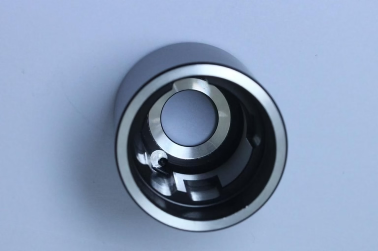
A collapsible core solves the same problem from the inside. The core does not pull out as one solid pin. It breaks into segments that close inward on a central pin, shrinking the effective diameter until the molded part clears. Then the part ejects with no side movement at all.
The trade is accuracy. You replace a simple solid pin with a stack of ground segments, each with a sliding interface. Everything about the tool now depends on how well those interfaces fit and how evenly the segments wear.
That is the design conversation. If the undercut runs around the full circumference of a bore, the collapsible core mold undercut solution is usually the shortest path. If the undercut is a single localized hook on one side, a lifter is still cheaper.
- 1Full 360° undercutInternal thread, ring groove or recess around a bore — strong candidate.
- 2Localized undercutOne hook or window on one side — a lifter or slide often costs less.
- 3No room for slidesSmall cavity inserts with no travel space push you toward a collapsing core.
Inside a Collapsible Core: Segments, Pin and Travel
A typical core uses three to six segments arranged around a center axis. During injection, a central pin or wedge holds them expanded against each other. The segments carry the molded bore, so the joint lines land on the part surface. Six segments give a rounder bore but twice the joint lines of three. Threads usually run three or four segments so the thread form can be timed across the joint.
When the mold opens, the center pin retracts first. Each segment is guided inward along an angled face, either a dovetail, a T-slot or a straight angled slide. Collapse travel is small, often 0.5 mm to 2 mm radially, just enough to clear the undercut depth plus a safety margin. If the undercut is 0.8 mm deep, plan 1.2 mm to 1.5 mm of radial collapse.
Timing matters more than travel. The pin must clear before the segments move, and the segments must fully collapse before ejection starts. A hardened wear plate or a guided cage sets that sequence. Skip it and the segments drag on the part, marking the bore and wearing the angled faces.
Segment interfaces are where the tool lives or dies. A gap of 0.01 mm at the joint shows as flash on the molded part, and flash on an internal thread is a rework job, not a trim job. Mating faces are usually ground and matched in pairs, then numbered so they go back in the same orientation after service.
Face contact should be high, above 80% by bluing check. Low contact means point loading, and point loading means the segments peen and lose their fit within a few thousand cycles.
- 1Collapse travelUndercut depth plus 0.4-0.7 mm of clearance is a normal starting point.
- 2Segment count3-4 for threads, 4-6 for round bores with tight ovality limits.
- 3Joint contactTarget above 80% face contact; check with bluing at assembly.
When a Collapsible Core Is the Wrong Choice
Collapsing cores need a bore to collapse into. The molded part must be a closed or nearly closed loop around the core, and the core body must have room to shrink. An undercut on the outside of a part is a different problem; there the cavity side has to move, and a slide or a split cavity is the answer.
Wall thickness and material stiffness matter too. Glass-filled nylon and PBT fight the collapse because the molded ring grips the segments. If the part is stiff and the undercut is deep, ejection force climbs and the segments wear faster. In those cases a lower collapse angle and more segments spread the load.
Cycle time is the other limit. Each cycle adds a collapse and reset stroke, and the segments need to return to a repeatable position before the next shot. On high-cavity tools this sequence is handled by the machine or a sequence plate. A 16-cavity cap tool with collapsible cores needs a well-tuned ejector and return system, not just good segments.
Size caps the technology from both ends. Very small cores under 8 mm bore are hard to segment because the segments become thin and fragile. Very large cores, say above 150 mm bore, can be segmented, but the mass of the segments and the required travel push you toward hydraulic actuation and a heavier base.
If the undercut is shallow, under about 0.3 mm, a flexible core or a bump-off sometimes works and costs far less. Try that first if the material is soft like PP or PE and the part tolerance is loose.
- 1External undercutCollapsible cores act inward; outside features need slides or splits.
- 2Bore under 8 mmSegments get too thin to hold tolerance and survive cycles.
- 3Shallow soft-material undercutBelow roughly 0.3 mm, try a flexible or bump-off core first.
Machining Precision That Decides Part Quality
Everything the part measures comes from the segment set. Bore diameter, ovality, thread pitch diameter, concentricity to the outside wall. If the segments are made to ±0.02 mm, the molded bore will drift more than that once you add shrink, wear and thermal growth. Tooling work is usually held tighter than the part print for that reason.
At GreatLight, core segments are machined on 16 simultaneous 5-axis machining centers, with a 4,000 mm maximum processing size when the core body is large. Angled mating faces, dovetail guides and thread forms on a curved segment are single-setup features on a 5-axis machine, which keeps the joint geometry consistent across the set. General tolerance is ±0.005 mm, with fine ground surfaces at Ra 0.2-0.8 μm on sliding faces.
Material choice follows the same logic. Hardened tool steel for long runs, and for the segments themselves, since they slide against each other every cycle. Copper alloys such as beryllium copper appear on core tips or cooling inserts where heat has to leave fast. Stainless grades like 420 or 440C show up on cores for medical and corrosive-resin jobs.
Surface finish on the molded bore is not just about the part. A rough sliding face wears a mating face. Polished guides at Ra 0.2-0.8 μm hold their fit longer than as-machined faces at Ra 1.6-3.2 μm.
- 1Segment set toleranceHold the set to ±0.005 mm where the part print is ±0.05 mm.
- 2Sliding facesGrind and polish to Ra 0.2-0.8 μm to control wear.
- 3Thread formCut or grind the thread form on the segment, then match the joint.
Cooling, Lubrication and Wear Surfaces
A collapsible core is a stack of sliding parts sitting in the hottest zone of the tool. Cooling has to reach the segment bodies, not just the cavity. Baffled water lines or a beryllium copper core tip pull heat out of the bore area. If the core runs hot, the segments grow, the fit tightens, and the collapse stroke binds.
Lubrication is a maintenance item, not an afterthought. The angled faces and the center pin need a high-temperature grease that survives the mold environment. Grease channels or grooves in the pin help carry lubricant to the sliding surfaces. On a well-run tool, the core is pulled and re-greased on a set cycle count, not when something breaks.
Wear shows up first as flash at the segment joints. A thin witness line on the molded bore is an early signal. If the line widens, the segments have lost face contact and need re-matching or replacement. Track it with a bore measurement at the same points each service interval.
Nitriding or a hard coating on the sliding faces is common for glass-filled resins. It raises surface hardness and cuts galling between similar steels. Coatings add cost, so they earn their place on long-run tools or abrasive materials, not on a 5,000-piece bridge tool.
- 1Cool the segmentsBaffled lines or a copper tip; keep the core near cavity temperature.
- 2Grease on a scheduleSet a cycle count for service, not a reaction to flash.
- 3Watch the joint lineA widening line on the bore means lost face contact.
How Core Quality Is Checked Before It Ships
A segment set is checked as an assembled unit, not as six separate parts. Each segment is measured on a CMM against the 3D model, then the set is assembled on its pin and the bore is measured again in the collapsed and expanded positions. Diameter, ovality and concentricity are recorded.
Function comes next. The core is cycled on a bench fixture or in the mold to confirm collapse travel, return position and repeatability. Return position is the one that bites. If the segments do not come back to the exact expanded diameter, the next shot is out of tolerance or flashes.
At GreatLight, inspection is 100% before shipment, covering raw material check, in-process monitoring and final inspection, with reports on request. The shop holds ISO 9001:2015, IATF 16949:2016 for automotive work, ISO 13485:2016 for medical devices and ISO 27001:2022 for information security.
For automotive connector and housing work, the tooling package usually includes first-article inspection reports and a dimensional layout tied to the part drawing. That record is what makes a tool transferable when the program moves to another plant or another molder.
- 1Measure assembledCMM the set on its pin, expanded and collapsed, not loose segments.
- 2Cycle the functionConfirm travel and return position on a bench fixture.
- 3Keep the recordLayout reports and material certs travel with the tool.
Collapsible Core vs Unscrewing vs Side Action
Use this as a first screen. Confirm with a mold flow and a tooling review before cutting steel.
| Criterion | Collapsible core | Unscrewing core | Side-action slide |
|---|---|---|---|
| Undercut type | Full internal thread or ring groove | Continuous internal thread only | Local hook, window, external tab |
| Cycle impact | Short collapse stroke, seconds | Motor or rack rotation, longest | Slide travel each cycle |
| Tooling footprint | No side space needed | Gear train or motor on tool | Cavity space for slide travel |
| Thread quality | Good form, joint lines on thread | Best thread, no joint lines | Not applicable |
| Maintenance driver | Segment interface wear | Gear, bearing and thread wear | Wear plates and cam surfaces |
| Best part size | Bores roughly 8-150 mm | Small to medium threaded caps | Any size with free side space |
| Relative tool cost | Medium to high | High | Low to medium |
Which Undercut Method to Pick
If the undercut runs around an internal bore and there is no room for side hardware, choose a collapsible core mold undercut solution. If it is a continuous internal thread on a cap with a free tool layout, unscrewing gives the cleanest thread. If it is a single localized hook or an external tab, pick a side-action slide and keep the tool simple.
Collapsible Core Questions Engineers Ask
How many segments should a collapsible core have?
Three or four for internal threads, because the thread form has to be timed across each joint. Four to six for plain round bores where ovality matters more than joint count.
More segments give a rounder bore but more joints to match and more sliding faces to wear. Start with the lowest count that holds the ovality callout.
What collapse travel is needed for a 1 mm deep undercut?
Plan 1.4 mm to 1.7 mm of radial travel: the undercut depth plus 0.4 mm to 0.7 mm of clearance. The clearance covers segment wear, thermal growth and any slight return-position error.
Tighter travel is possible but leaves no margin. Once the joints wear, the core drags on the part during ejection and marks the bore.
Can a collapsible core mold a glass-filled part?
Yes, but expect faster wear. Glass-filled nylon and PBT grip the segments and raise ejection force, so the angled faces and center pin work harder.
Use hardened steel or a coated sliding face, drop the collapse angle slightly, and shorten the service interval for greasing and joint inspection.
What part tolerance can a collapsible core hold?
The molded bore follows the segment set. If the set is machined and matched to ±0.005 mm, the molded bore can normally hold a part print around ±0.05 mm, depending on resin shrink and gate position.
The joint lines set a practical floor on roundness. If the print calls for a perfectly round bore with a tight ovality limit, more segments help but do not remove the joints.
How do I know when the segments need replacing?
Flash at the joint lines is the first sign. A thin witness line on the molded bore that widens shot to shot means the faces have lost contact.
Measure the assembled bore at fixed points each service interval. When it drifts past the tool tolerance, re-match the faces or replace the worn segments rather than running to failure.
Does a collapsible core need a special molding machine?
No. The collapse is driven by the mold's own ejector or return system, or by a hydraulic cylinder on the tool. The press just needs a clean sequence for open, collapse and eject.
High-cavity tools need a well-tuned ejector and return plate so every core resets to the same expanded diameter before the next shot.
Send Your Undercut Part for a Tooling Review
Upload the part model and get a quotation with free DFM analysis within 12 hours. Production can start within 24 hours, and parts ship in 3-5 days.
12-hour quote±0.005 mm100% inspectionNDA on request
More Tooling and Machining Notes
We publish setup notes, tooling trials and inspection data from the factory floor.











