Aiming at the problem of cutting Ti6Al4V titanium alloy thin-walled housings, the structural and dimensional requirements of the parts were analyzed by compiling reasonable process routes and CNC programs, and selecting tools, cutting parameters and reasonable tooling fixtures, machining precision. The parts have been insured. Provide reference for CNC turning processing of these thin-walled parts.
01. Preface
Ti6Al4V titanium alloy is a material with high strength, low density and good heat and corrosion resistance. It is widely used in aerospace, automobile, medical equipment and other fields.[1]. Due to its material characteristics, after heat treatment and strengthening, the hardness reaches 320HBW and the tensile strength is not less than 1200MPa. During the treatment, there will be problems such as enhanced crushing, tearing and peeling, which will make the cutting treatment more severe. difficult. Therefore, the Ti6Al4V cutting process is studied. It is of great importance to improve the efficiency and quality of treatment.
02. Performance analysis of Ti6Al4V
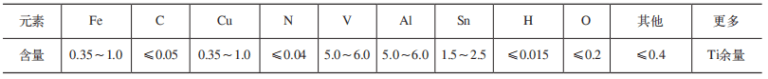
The difficulty of cutting Ti6Al4V is mainly determined by the chemical composition, metallographic structure and mechanical properties of the material itself. its chemical composition[2]See Table 1 and mechanical properties in Table 2.
Table 1 Chemical composition of titanium alloy Ti6Al4V (mass fraction) (%)
Table 2 Mechanical properties of Ti6Al4V titanium alloy

03. Introduction to thin-walled housing parts and analysis of implementation difficulties
The parts of the thin-walled housing are shown in Figure 1 and the dimensions of the parts are shown in Figure 2. This part is a large diameter thin-walled part. It is mainly composed of a thin-walled straight cylinder, several flanges, bevels and grooves on the outer diameter. The part material is Ti6Al4V titanium alloy. A and the inner diameter (2013.7 ± 0.5) mm, the maximum outer diameter is (2108.7 ± 0.5) mm, the thinnest wall thickness is (6 ± 0.5) mm, the height is (678 ± 0.5) mm and the surface roughness value Ra≤3.2 μm. The flatness of the parts is ≤0.2mm and the roundness is ≤0.5mm. Since the inner and outer diameters of the parts have complex special-shaped cross sections, CNC turning is more difficult.

Figure 1 3D model of parts

Figure 2 Room size
04. Processing technology plan
Through the analysis of the workpiece structure and processing difficulties, the processing technology plan was formulated as shown in Table 3.
Table 3 Treatment Technology Plan

05. Implementation of the process plan
5.1 Tool selection
Because after heat treatment of titanium alloy, the surface of the blank is hard and the diameter is large and there is an ellipse. Therefore, the cutting force is very large during turning and the tool is prone to chipping. YG8 carbide tools with strong impact resistance are used for rough turning, and CNMG160612-GJ VP10RT and RPMT10T3MOE-JS VP15TF coated carbide inserts are used for semi-finishing and finishing turning.[3]。
5.2 CNC program for finished turning parts
According to the analysis of the processing difficulties of the part and the process plan, the geometry of the part is relatively complex, so computer-aided programming (CAM) is used. The main steps are as follows.
(1) Part processing and process analysis includes confirming part size, tolerance and precision requirements, confirming feeding routes, fixtures, measuring tools and cutting tools, as well as confirmation of the programming origin and programming coordinate system.[4]。
(2) Modeling of machined parts Use computers and software to establish three-dimensional models of parts.
(3) Processing parameter input includes selection of machine tool model, blank size, tool type, cutting quantity and other information (safety plan, tool path). tool, method of advancing and withdrawing the tool, cooling method, etc.).
(4) Generation and improvement of tool paths. Based on the geometric information and process information, the system automatically performs calculation and arrangement to generate tool paths. If the tool path is not reasonable, it can be improved through human-machine interaction.
(5) Trajectory simulation and first part trial processing. Introduce the program into the equipment and let the equipment run dry to check the accuracy and rationality of the tool path. To check the machining accuracy of the program, it is necessary to carry out a trial processing of the first part to discover the flaws and defects in the program, modify them and compensate for them.
(6) Further program processing converts the toolpath file into a program that can be accurately executed by the CNC lathe. The small thin end and the outer circle are shown in Figure 4.

Figure 4 Small Fine Turning End and Outer Circle
Taking the finishing of cylindrical groove 1 as an example, select a ball groove tool with a tool width of 6mm and a tool tip of R3.0mm. The procedure is as follows.

Use a sharp 50° knife with an R1.2mm tip for the precision rotating inner circle of the small end. The procedure is as follows.

The finished rotating big end and outer circle are shown in Figure 5.

Figure 5 Finish turning the big end and outer circle
Use a ball bearing tool with a tool width of 6mm and a tool tip of R3.0mm to finish turning the outer circle. The procedure is as follows.


For precision large-end turning, a spherical groove milling cutter with a blade width of 6mm and a tip of R3.0mm is used for the inner circle. The procedure is as follows.

5.3 Cutting parameters
According to the requirements of workpiece material, dimensional accuracy and surface roughness, combined with the cutting values recommended in the tool manual.[5]The cutting parameters of the selected tool are shown in Table 4.
Table 4 Tool cutting parameters

06. Verification of processing
After analyzing the CNC turning processing of titanium alloy case, the process route, CNC program, tools and cutting parameters were reasonably selected. The strategy of “low and medium speed, faster feed and larger depth of cut” is used during rough turning, and the cutting method of “high speed, slower feed and smaller depth of cut” is used during finishing turning, which can effectively ensure the machining precision of parts. Inspection records of key dimensions of the finished titanium alloy case are shown in Table 5 and the finished parts are shown in Figure 6.
Table 5 Inspection records of key dimensions of titanium alloy case (unit: mm)


Figure 6 Finished parts
07.Conclusion
This article analyzes the problems and difficulties of large-diameter titanium alloy case turning process, compiles reasonable processing techniques and CNC programs, and selects appropriate tools and cutting parameters to achieve smooth turning of parts. . Since the workpiece diameter is larger, the wall thickness is thinner, and the dimensional accuracy must be high, special tooling is designed to ensure the processing quality of the product. After an actual processing check, it solved the CNC. Large diameter titanium alloy case turning problem.
Daguang focuses on providing solutions such as precision CNC machining services (3-axis, 4-axis, 5-axis machining), CNC milling, 3D printing and rapid prototyping services.


