
China CNC Machining Fabrication Process, Step by Step
This page walks through how a part moves from a 3D file to a finished, inspected component in a China cnc machining fabrication shop. It is written for design engineers and sourcing engineers who need to judge whether a supplier's process is real or just marketing. You will see what happens at each stage, where parts usually go wrong, and which checks matter before you release a drawing.
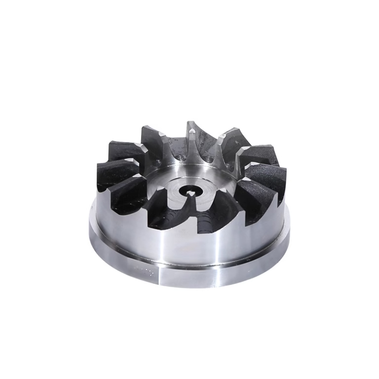
What the Fabrication Process Actually Covers
Six stages, one drawing, and a paper trail that has to match the part.
DFM Review: The Process Starts With a Conversation
A quote is not the first step. The first step is a manufacturability review of your model, and it should be done by a person who runs machines, not only by quoting software. At GreatLight, an applications engineer reads every RFQ and looks at wall thickness, internal corner radii, deep-hole aspect ratios, thread engagement, and how the material behaves when it is cut. Automated quoting tools are fast, but they miss features that look fine on screen and fail when the tool reaches them.
That review is where cost is really decided. A 0.5 mm internal corner in a 12 mm deep pocket forces a small end mill, and a small end mill has to run slower with lighter passes. The part may still be made, but the cycle time doubles. Move the radius to 2 mm and the same pocket machines with a standard tool. Thin floors deflect, deep holes need peck cycles, and a thread too close to a wall can crack after anodizing.
We return a marked-up model with the flagged features, not a list of complaints. Most responses come back within 12 hours, together with the quotation. Design changes are the customer's call; our job is to show the trade-off in time and tooling before the first chip is cut.
- 1Corner radiiKeep internal radii at 1/3 of pocket depth or larger to avoid long, slow small-tool passes.
- 2Wall thicknessBelow 0.8 mm in aluminum, plan for a support strategy or a soft-jaw fixture.
- 3ThreadsLeave at least one thread diameter of material around a tapped hole.
- 4TolerancesCall out only the features that need ±0.005 mm; blanket tight tolerances raise cost.
Material Selection, Verification, and Preparation
The material certificate matters as much as the grade name. A 6061-T6 plate and a 6061-T6 extrusion behave differently after machining. Plate is more stable and holds flatness better; extrusion can move after the skin is cut. For a housing with a flatness callout, we start from plate. For a simple bracket, the extrusion is cheaper and fine.
Incoming stock is checked before it goes to a machine. We verify grade with a mill certificate and, where the drawing demands it, run a hardness or composition check. Aluminum 7075, 17-4PH stainless, Ti-6Al-4V, and Inconel each carry their own cutting behavior: 7075 machines clean but is notch-sensitive, 17-4PH in the H900 condition will fight a carbide insert if feeds are wrong, and Ti-6Al-4V needs low surface speed and high coolant pressure to keep heat out of the edge.
Pre-cut stock is squared and faced so the first setup has a true reference. The wrong starting blank shows up later as an out-of-square part that no amount of finishing will fix. For castings and forgings, we check for scale, porosity, and enough stock on the machined faces.
- 1Plate vs. extrusionPlate for flatness and stability; extrusion for simple, low-cost brackets.
- 2CertificatesMill cert on file for every heat lot; extra testing on request.
- 3Pre-machiningSquare and face the blank so setup datums are real.
Machining Execution: Choosing the Right Machine
Machine choice follows the geometry, not the other way around. A part with features on five faces in one setup belongs on a 5-axis center. A long shaft with a cross-hole belongs on a mill-turn center, where turning and milling happen without losing concentricity. Simple plates run faster on a 3-axis mill. GreatLight runs 127 CNC machines, including 16 simultaneous 5-axis centers, 16 mill-turn centers, and 12 four-axis mills.
The benefit of 5-axis is fewer setups. Every re-fixture adds a small position error, and on a part with eight tight hole locations, those errors stack. Cutting five faces in one setup keeps the datums consistent. For parts up to 4,000 mm, the large-travel machines handle long rails and frames; the 750 × 1,150 × 550 mm and 600 × 600 × 600 mm machines cover most mid-size work.
In-process checks are built into the route. The operator measures critical features after roughing and again after finishing, before the part leaves the machine. If a dimension drifts, we stop and adjust the offset rather than run the whole batch and sort later. That is how a 99.99% qualification rate is held without sorting at the end.
- 15-axisMulti-face parts, contoured surfaces, tight true position across faces.
- 2Mill-turnShafts, bushings, fittings with cross-features and coaxial bores.
- 33-axisPlates, covers, brackets with features on one or two faces.
Machine Selection by Part Type
Match the geometry to the machine before you compare price.
| Part type | Machine | Why |
|---|---|---|
| Housing, 5 faces | 5-axis center | One setup, datums stay consistent |
| Shaft with cross-hole | Mill-turn center | Turning and milling without re-fixture |
| Flat cover plate | 3-axis mill | Fast, low cost, easy to fixture |
| Long rail, up to 4,000 mm | Large-travel mill | 4,000 × 400 × 150 mm travel |
| Round flange, Ø400 mm | Rotary table | Continuous indexing, no re-chuck |
| Prototype, 1 pc | 3-axis or 5-axis | No minimum order quantity |
Post-Processing and Surface Finishing
Machining leaves tool marks, burrs, and residual stress. Finishing removes them and, in some cases, changes the dimension. Anodizing builds a layer; hardcoat anodizing can add 25–50 μm per surface, which matters on a press-fit bore. Electroless nickel adds a uniform layer even inside holes. We ask which dimensions must survive the coating before the parts go out.
Common finishes we run include clear, color, hardcoat, and conductive anodizing; electroless nickel, zinc, silver, and gold plating; powder coating and black oxide; bead blasting, tumbling, brushing, and polishing. Laser marking is available down to 1.5 mm character height. As-machined surfaces sit around Ra 1.6–3.2 μm, standard fine finishes reach Ra 0.8–1.6 μm, and lapped or polished surfaces go to Ra 0.2–0.8 μm.
Deburring is not optional. A burr on a medical instrument edge or an internal oil passage is a functional defect. Edges get a controlled break, usually 0.1–0.2 mm, unless the drawing calls for a sharp edge. For parts that go into an assembly, we mask threads and sealing faces before coating so the fit still works after plating.
- 1MaskingThreads and sealing faces protected before anodizing or plating.
- 2Coating growthHardcoat anodizing adds 25–50 μm per surface; allow for it in the bore size.
- 3Edge breakDefault 0.1–0.2 mm unless a sharp edge is specified.
Metrology, Documentation, and Shipping
Inspection is 100% before shipment, and it covers three points: incoming material, in-process dimensions, and final release. CMM reports, first article inspection reports, and material certificates are available on request. For medical and automotive work, the documentation package is part of the product. A part that measures well but has no paper trail is a problem at audit time.
Tolerance is held at ±0.005 mm (±0.0002 in) on features that call for it. Not every dimension needs that. We mark up the drawing so the tight tolerance goes where it matters and the rest runs at a sensible default. That keeps cost down and reduces the chance of a false reject at inspection.
Packing follows the part. Precision surfaces get separated, threads get protection, and small runs can ship as kitted sets with the hardware sorted. GreatLight holds ISO 9001:2015, IATF 16949:2016, ISO 13485:2016, and ISO 27001:2022. The information security certificate matters if your drawings are confidential; an NDA is available on request. Parts typically ship in 3–5 days after production starts, and the historical late-delivery probability is below 2%.
- 1ReportsCMM, FAIR, and material certificates on request.
- 2Tolerance±0.005 mm where specified; sensible defaults elsewhere.
- 3ConfidentialityISO 27001:2022 controls; NDA available on request.
Questions Engineers Ask Before Releasing a Drawing
What file formats do you need for a quote?
STEP and IGES cover most parts, and native files from SolidWorks, Inventor, or Fusion 360 also work. Add a 2D PDF with the tolerance callouts, thread specs, and finish notes. A 3D model alone does not carry the critical dimensions.
If the model and the drawing disagree, we ask before quoting rather than guessing.
How tight can the tolerance be on a production run?
We hold ±0.005 mm (±0.0002 in) on specified features. That level belongs on fits, bores, and hole locations that actually need it. Putting it on every dimension raises cost and inspection time without improving the part.
Send the drawing and we will mark which features should carry the tight tolerance.
Do you machine prototype quantities?
Yes. There is no minimum order quantity, so one prototype is fine, and the same process scales to 10,000+ part runs. Prototype and production parts run on the same machines, which means the geometry you approve is the geometry you get in volume.
Quotation and free DFM analysis come back within 12 hours, and production can start within 24 hours.
Which materials do you stock or source?
Aluminum 6061, 6061-T6, 2024, 5052, 5083, 6063, 6082, 7075, and ADC12; stainless 303, 304, 316, 316L, 420, 430, 431, 440C, and 17-4PH; steel 1018, 1045, 4130, 4140, 4340, A36, and tool steel. Copper and brass include C101, C103, C110, beryllium copper, C27400, C28000, and C36000.
Titanium TA1, TA2, TC4 (Ti-6Al-4V), Inconel, and magnesium AZ31B / AZ91D are available, along with plastics such as ABS, PC, PMMA, POM, PA, PEEK, PP, HDPE, and carbon fiber.
Can you keep the drawings confidential?
Uploads are secure and confidential, and we work under ISO 27001:2022 information security controls. An NDA is available on request if your program needs one before files are shared.
Production data stays inside the three wholly-owned plants in Dongguan and Singapore.
What happens if a part is out of tolerance?
The operator stops the run and reports it before the batch is finished. We re-measure the feature, check the offset, and decide whether the part can be reworked or must be remade.
Inspection is 100% before shipment, so the goal is to catch drift in-process rather than after the batch is packed.
Send a Drawing, Get a DFM Review
Upload your STEP file and drawing. An applications engineer reviews the geometry and returns a quotation with free DFM analysis within 12 hours.
12-hour quote±0.005 mm tolerance100% inspectionNo minimum order quantity









