
Carbon Fiber CNC Machine Guide
This guide is for design engineers and buyers who need to cut CFRP parts, not just quote them. It covers what a carbon fiber CNC machine has to handle, which tooling and parameters survive the abrasive dust, and when milling is the wrong process. Read it and you can judge whether a shop's setup fits your part.
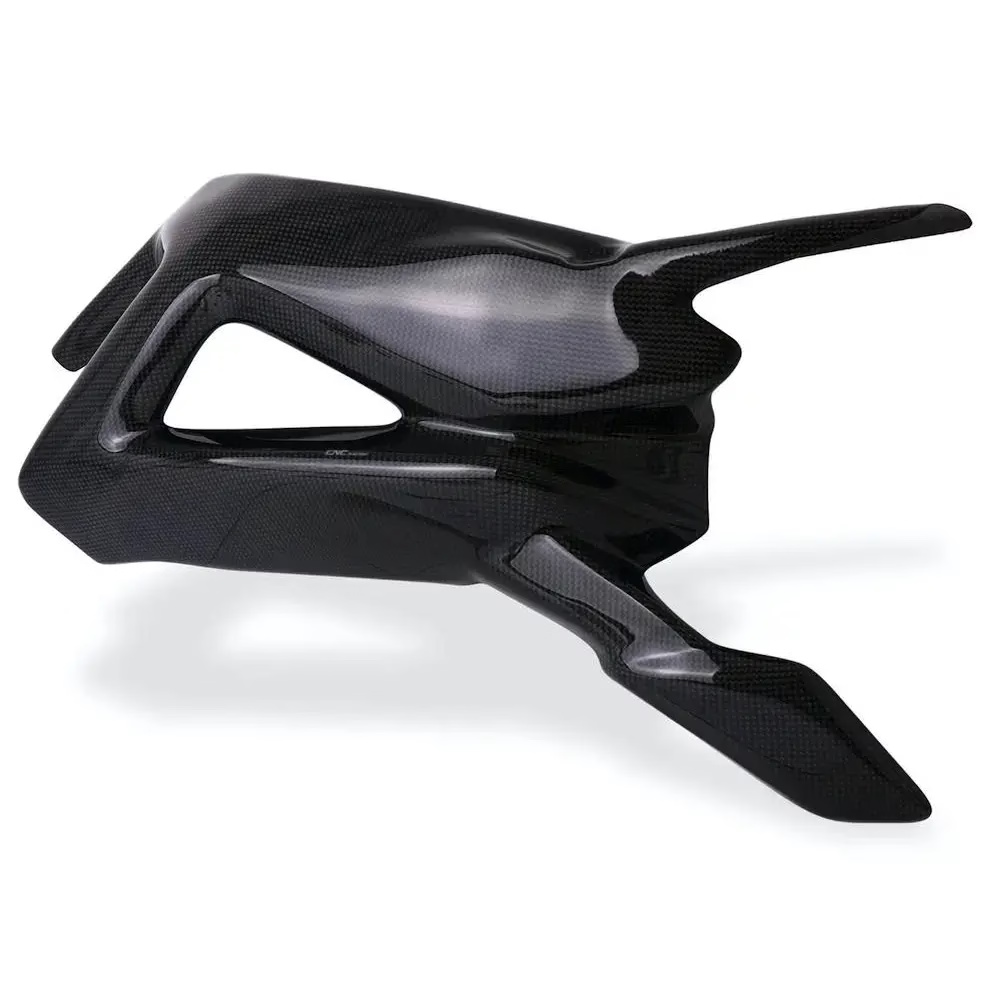
Machining CFRP without wrecking the part
A carbon fiber CNC machine is not a metal mill with a different tool in the spindle. The material decides almost every choice downstream.
Why carbon fiber fights back against a spindle
The laminate structure is the first thing to understand. Fibers run in one direction inside a resin matrix, so stiffness and strength change with direction. A cutter that bites cleanly across the fibers can tear along them. Push a tool too hard and the top plies lift, delaminate, or splinter while the resin smears and burns.
Abrasion is the second problem. Cured carbon is harder than most aluminum alloys and it grinds an edge down fast. Uncoated carbide that lasts a full shift in 6061 may dull in twenty minutes here. Heat stays in the cut because the polymer cannot pull it away the way metal does.
Dust is the third. The chips are fine, conductive, and bad for skin and lungs. A carbon fiber CNC machine needs sealed ways, a vacuum hold-down or dedicated fixturing, and extraction at the cutter, not a shop vac in the corner.
None of this means the material is unmachinable. It means the process window is narrow, and the machine, tool, and fixture have to be chosen together rather than one at a time.
What the machine itself has to provide
Rigidity matters more than raw spindle speed. Thin-walled CFRP parts deflect under cutting force, and a machine with play in the ways will rub rather than cut. Linear guides and a stiff frame keep the tool engaged instead of bouncing on the fiber.
Five-axis capability earns its place on contoured parts. A hole drilled at an angle to the surface, a tapered edge on a curved panel, or a trimmed flange on a complex shell all need the tool normal to the surface. Repositioning the part between setups adds error and risks chipping the edge each time it is clamped.
Control resolution and thermal stability decide whether you hold tolerance. Composite panels move with temperature, so a shop that machines a 1,200 mm part in a warm room and inspects it in a cool one will fight the numbers. GreatLight runs 16 simultaneous five-axis machining centers with a Ø400 mm rotary table and travels up to 4,000 × 400 × 150 mm, so long panels and compact brackets both fit.
Dust extraction is part of the machine spec, not an accessory. Sealed enclosures, extraction at the nozzle, and filtered collection keep the abrasive dust out of the slides and off the operator.
Starting parameters for CFRP milling
Typical ranges for diamond-coated or PCD tooling on a rigid machine. Tune on scrap before cutting a finished part.
| Operation | Tool | Typical range |
|---|---|---|
| Rough profiling | Diamond-coated burr, 6–12 mm | Spindle 8,000–12,000 rpm |
| Finish edge trim | PCD or diamond-coated end mill | Feed 1,500–3,000 mm/min |
| Hole drilling | Diamond-coated drill, 118–140° point | Peck 0.5–1.0 mm per cycle |
| Pocketing | Compression router, 6–10 mm | Step-down 1–2 mm |
| Countersink | Diamond-coated chamfer tool | Low feed, high rpm |
| Dust control | Extraction at cutter plus enclosure | Air velocity checked at nozzle |
Tooling, clamping, and the order of operations
Tool choice comes down to edge geometry and coating. Diamond-coated carbide and PCD hold an edge long enough to be economical, and they cut cleanly rather than pushing fibers aside. Two-flute and compression routers work well on laminated panels because they balance the load on both faces and reduce splintering at the exit side.
Fixturing is where most CFRP jobs are won or lost. Vacuum tables spread the clamping load and avoid point stress, which is what causes delamination under a clamp. For thin panels, a sacrificial backing board supports the exit side and stops the last plies from breaking out. For curved parts, a matched support nest holds the shape while the tool trims the edge.
Operation order should be planned around the part's weak points. Do the heavy material removal while the blank still has enough stiffness, then move to finish passes on the edges and surfaces. Drill holes after the faces are stable. Deburr and seal cut edges before the part leaves the machine, because exposed fiber ends fray and absorb moisture.
Coolant is usually avoided. Flood coolant wicks into cut edges, and wet dust turns into a paste that clogs extraction. Most shops run dry or with a light air blast, then clean the part thoroughly before inspection.
When milling is the right answer, and when it is not
Milling suits flat panels, brackets, ribs, frames, and trimmed shells where the layup is already cured. It also suits one-off and low-volume work that cannot justify a mold. If your part has tight bores, flat mating faces, or a trimmed outline that has to match a mating housing, a machined CFRP part gets there without tooling cost.
Milling is the wrong answer when the geometry is a deep closed shell, a hollow duct, or a part with undercuts inside a cavity. Those need a mold, and the part should be laid up near net shape. Milling is also a poor fit for high-volume simple parts, where compression molding or resin transfer molding wins on cost per piece.
A hybrid route is common in practice. Lay up or buy a near-net panel, then machine the critical edges, holes, and interfaces. This keeps the fiber continuous where strength matters and gives you the dimensional control where it counts. Tell us the load path and the interface dimensions, and we can say which features should be molded and which should be cut.
Tolerance is the other deciding factor. GreatLight holds ±0.005 mm on machined features, but a cured laminate will still move with humidity and temperature. If a drawing calls for a tight fit across a long unsupported span, expect to negotiate where the tolerance is applied.
Inspection, finish, and what to send us
Inspection on CFRP is mostly dimensional plus visual. Calipers, micrometers, and CMM checks confirm the features, while the eye catches delamination, fiber pull-out, and resin burn at the edges. A part can hold its numbers and still fail because the surface tells a different story.
Finishing is limited but useful. Cut edges can be sealed or lightly sanded, and bead blasting gives a uniform matte face for cosmetic parts. Paint and primer bond better after a light abrade and clean, and laser marking works on flat areas where a 1.5 mm minimum character height fits. Anodizing and plating do not apply to polymer composites.
When you send a job, include the layup or fiber orientation, the drawing with datum callouts, and any note on which surfaces are cosmetic. Add the interface dimensions that matter and the ones that can float. That lets us plan the order of operations around your load path instead of guessing.
Uploads stay confidential and an NDA is available on request. We machine from one prototype to 10,000+ part runs, with quotation and a free DFM analysis inside 12 hours.
Common questions
Why is five-axis needed for CFRP parts?
Cured composite parts usually have contoured surfaces and features at odd angles. Five-axis motion keeps the tool normal to the surface, which cuts fibers cleanly instead of tearing them.
It also lets you reach the back side and trim edges without releasing the part. Every reclamp risks chipping a finished edge, so fewer setups means fewer rejects.
Can you hold ±0.005 mm on a cured laminate?
On machined features such as holes, slots, and trimmed outlines, yes. Our machines hold ±0.005 mm and we inspect 100% before shipment.
The limit is the material, not the machine. A long unsupported panel will move with temperature and humidity, so tight fits across long spans need a discussion about where the tolerance is applied.
What tooling lasts on carbon fiber?
Diamond-coated carbide and PCD. Both resist the abrasion that dulls uncoated carbide quickly.
Two-flute and compression routers are common for panel work because they reduce splintering on the exit side. Bring a spare edge to the setup, because the wear rate is real.
Is coolant used when machining carbon fiber?
Usually not. Flood coolant wicks into cut edges and turns the fine dust into a paste that clogs extraction.
Most jobs run dry with a light air blast and extraction at the cutter. The part is cleaned before inspection.
Which features should be molded instead of machined?
Deep closed shells, internal undercuts, and hollow ducts. Those need a mold because the tool cannot reach inside.
For most parts, lay up near net shape and machine the critical edges, holes, and mating faces. That keeps fiber continuous where the load is.
How fast can you turn around a CFRP job?
Quotation and free DFM analysis come back within 12 hours, and production can start within 24 hours of approval.
Parts typically ship in 3–5 days depending on geometry and quantity. There is no minimum order quantity, from one prototype upward.
Send us your CFRP part and drawing
Quotation and free DFM analysis within 12 hours. Tell us the layup, the interfaces that matter, and which surfaces are cosmetic.
12-hour quote100% inspection±0.005 mmNDA on request









