
Basic Knowledge of a CNC Metal Milling Machine
A working engineer's view of what a CNC metal milling machine actually does: how the cutter removes metal, how many axes you need, and where the process stops being economical. Written for designers and buyers who have to sign off on a drawing.
In this article
- 1
- 2
- 3
- 4
- 5
- 6
How a CNC Metal Milling Machine Removes Metal
Milling is subtractive. A rotating cutter with multiple teeth is fed into a solid block, and each tooth shears off a chip. The machine controls three things at once: spindle speed, feed rate, and depth of cut. Get those three into the right range for the material and the cut is stable. Push any one of them too far and you get chatter, tool wear, or a scrapped part.
The control reads G-code generated from a CAM file, which itself comes from your 3D CAD model. The CAM step decides cutter size, stepover, lead-in, and toolpath order. Two shops can run the same model and get very different cycle times because of those choices, not because of the machine.
Chip evacuation matters more than most people expect. Aluminium 6061 clears easily and can run at high feed. Titanium Ti-6Al-4V and Inconel hold heat in the cut, so cutters need lower surface speed, heavier coolant, and shorter tool life. If chips recut, the surface finish drops and the tool breaks early.
Rigidity sets the real limit. A long thin tool hanging 5 × D out of the holder will deflect under load, no matter how good the control is. Shorten the gauge length, use a shrink-fit holder, or accept a lighter depth of cut. That is a fixturing and tooling decision, not a software one.
Three, Four, and Five Axes on a CNC Metal Milling Machine
A three-axis machine moves the table in X, Y, and Z only. The part is cut from one direction per setup. A part with features on four sides needs four setups, four fixtures, and four chances to lose datum alignment. That is fine for flat plates, housings, and simple brackets.
Add a fourth axis and the workpiece rotates about one axis, usually A. Now you can cut around a cylindrical part or reach multiple faces with fewer setups. Typical four-axis work is shafts, connectors, and parts that are mostly rotational with milled flats.
Five-axis machines tilt and rotate the part or the spindle, so the cutter can approach from almost any direction. Undercuts, deep pockets with drafted walls, and impeller blades become reachable in one setup. GreatLight runs 16 simultaneous five-axis machining centers, which is where most of our complex geometry work lands.
More axes is not automatically better. A five-axis cycle costs more per hour, and the CAM programming takes longer. If the part has three orthogonal faces and loose tolerances, three-axis is the cheaper, faster answer. Choose by geometry, not by machine spec sheet.
Setup, Workholding, and Why They Decide Your Tolerance
Every setup adds error. Loosen a vise, move the part, re-clamp, and you have a new stack-up of fixture error, thermal drift, and probe uncertainty. That is why shops push work into one setup whenever the geometry allows it. Fewer setups means fewer places for the dimension to drift.
Workholding also limits how much material you can remove per pass. A thin wall flexes away from the cutter, so the wall springs back after the tool passes and cuts oversize. The fix is often a support, a softer finishing pass, or leaving more stock and coming back with a light cut.
Thermal behaviour is part of setup. A 300 mm aluminium plate warms as you rough it, and it moves. Rough in the morning, let it settle, then finish. On tight parts we hold ±0.005 mm, and that only survives if the sequence respects heat and clamping order.
For thin floors and tall ribs, a five-axis tilt lets the cutter use the flank of the tool instead of the tip. You get a stiffer cut at the same depth. It is one of the few places where axis count directly buys you dimensional control rather than just reach.
What a CNC Metal Milling Machine Cuts Well
Aluminium is the easy case. We run 6061, 6061-T6, 2024, 5052, 5083, 6063, 6082, 7075, and ADC12. It cuts fast, finishes clean, and holds a good surface. 7075 and 2024 are stronger but more prone to distortion after heavy material removal, so rough and finish passes are usually separated.
Stainless grades 303, 304, 316, 316L, 420, 430, 431, 440C, and 17-4PH all mill, but they work-harden. Keep the cutter moving and never let it rub. Steel grades 1018, 1045, 4130, 4140, 4340, A36, and tool steel behave more predictably and are common for structural parts.
Titanium TA1, TA2, TC4, plus Inconel and magnesium AZ31B / AZ91D sit at the difficult end. Titanium and Inconel need low surface speed and rigid setups. Magnesium cuts quickly but demands chip control because fine magnesium chips are a fire risk.
Plastics are a different problem. ABS, PC, PMMA, POM, PA, PEEK, PP, and HDPE are soft, so they melt, gum, and burr. Sharp single-flute cutters, high spindle speed, and air blast usually work better than flood coolant.
Where Milling Stops Making Sense
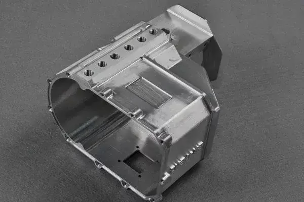
Milling is a poor fit for parts that are mostly a hollow shell with uniform wall thickness. A die-cast or vacuum-cast part gets there in one shot, and milling the same shape from solid wastes most of the stock as chips. If wall thickness is under about 1.5 mm across a large area, casting or sheet metal usually wins.
Very high volumes change the maths too. At 10,000+ parts a year, the cycle time of a milling operation starts to matter more than tooling cost, and casting or forging with a light finish pass becomes cheaper. Milling still owns the low and mid volume range because there is no tooling to amortise.
Milling also struggles with sharp internal corners. A rotating cutter has a radius, so every internal corner carries the tool radius unless you use a smaller tool or EDM. Designers who draw a true 90° internal corner force a second operation.
Surface finish has limits as well. We hold Ra 0.2–0.8 μm with fine finishing, Ra 0.8–1.6 μm as a high-quality standard cut, and Ra 1.6–3.2 μm as-machined. Mirror finishes on large curved faces are usually a polishing job after milling, not a milling result.
Axis Count, Tolerance, and Best-Fit Work
Ranges reflect the machines and tolerances GreatLight holds in production.
| Setup | Typical tolerance | Best-fit geometry | Watch out for |
|---|---|---|---|
| 3-axis | ±0.01 mm | Flat plates, brackets, simple housings | Multiple setups on 4-sided parts |
| 4-axis | ±0.01 mm | Shafts, connectors, milled flats on rounds | Rotary backlash on tight bores |
| 5-axis simultaneous | ±0.005 mm | Impellers, undercuts, drafted deep pockets | Higher hourly rate and CAM time |
| Mill-turn | ±0.005 mm | Parts mixing turned and milled features | Fixture access for long bores |
| Large travel | ±0.01 mm | Frames up to 4,000 mm long | Thermal drift over long cycles |
The Short Version
If your part has three orthogonal faces and normal tolerances, use a three-axis or four-axis setup and save the money. If it has undercuts, drafted walls, or features you cannot reach in one orientation, a five-axis CNC metal milling machine pays for itself in setups avoided.
Questions Engineers Ask
What tolerance can a CNC metal milling machine hold in normal production?
Across our 127 machines we hold ±0.005 mm (±0.0002 in) on tight work, and ±0.01 mm on general parts with larger features.
The achievable number depends on material, wall thickness, and how many setups the part needs. A rigid aluminium block in one setup is easier than a thin stainless housing in three.
When is five-axis worth the extra cost?
Use five-axis when the geometry cannot be reached from three directions, when a single setup removes a real alignment risk, or when the part needs a tilted cutter to stay rigid on deep walls.
If none of those apply, the extra hourly rate buys nothing. A three-axis machine cutting the same part will be cheaper and usually faster.
How do I choose between an as-machined and a fine finish?
As-machined sits at Ra 1.6–3.2 μm and is normal for brackets, internal faces, and anything painted or coated later.
Ra 0.8–1.6 μm is our standard high-quality finish for visible faces and sealing surfaces. Ra 0.2–0.8 μm is reserved for fine finishing passes, and it adds cycle time.
Does milling work for prototypes and small runs?
Yes. There is no minimum order quantity, so one prototype and a 10,000-part run both go through the same process.
Prototypes usually skip hard tooling entirely, which is why milling is the default for early design iterations.
What files do you need to quote a milled part?
A STEP or IGES model plus a 2D drawing with tolerances, datums, and finish callouts. Material grade and quantity help too.
We return a quotation and a free DFM analysis within 12 hours, and production can start within 24 hours after that.
How do you protect design data?
Uploads are secure and confidential, and we sign an NDA on request.
We hold ISO 9001:2015, IATF 16949:2016, ISO 13485:2016, and ISO 27001:2022, and every part is inspected before shipment.
Send Us Your Drawing
Upload a STEP file and get a quotation plus a free DFM analysis within 12 hours.
12-hour quote100% inspectionNo minimum order quantity
More From the Shop Floor
We publish setup notes, tooling trials and inspection data from the factory floor.











