127 Sets Processing 4000mm 127 Sets High-Precision CNC Lathes
15 Years of Experience

CNC Knowledge: An article deeply interprets processes / measurement problems of crankshaft oil holes

Mastering Deep Hole Drilling: Techniques for Precision Machining Success Deep hole drilling represents one of the most challenging yet essential processes in advanced manufacturing, requiring specialized techniques to overcome inherent obstacles and achieve stringent precision requirements. Understanding the fundamentals and complexities is critical for delivering high-quality components reliably. Defining Deep Holes and Classification In precision […]

cnc knowledge: an article provides a detailed explanation of the

Mastering Deep Hole Drilling: Techniques for Precision Machining Success

Deep hole drilling represents one of the most challenging yet essential processes in advanced manufacturing, requiring specialized techniques to overcome inherent obstacles and achieve stringent precision requirements. Understanding the fundamentals and complexities is critical for delivering high-quality components reliably.

Defining Deep Holes and Classification

In precision engineering, any cylindrical hole where the depth exceeds 10 times the diameter qualifies as a deep hole. This critical aspect ratio dictates the necessary equipment and methodology:

  1. General Deep Holes (L/D = 10-20): Typically processed using extended twist drills on robust drilling machines or radial drilling centers ("towers").

  2. Medium Deep Holes (L/D = 20-30): Often require dedicated deep hole drilling setups or modified tower functionality for stability.

  3. Special Deep Holes (L/D = 30-100+): Demand specialized deep hole drilling machines (e.g., gun drills, BTA systems) engineered for extreme depth-to-diameter ratios.

Schematic of a dedicated deep hole drilling machine essential for high L/D ratios. ### Core Challenges in Deep Hole Operations

The inherent difficulties stem from restricted access and physical constraints:

  1. Zero Visual Feedback: Operators must rely on secondary indicators: audible machining sounds, coolant flow pressure, load meters, vibration sensors, and chip appearance to monitor progress and diagnose issues.
  2. Heat Dissipation Limitation: Friction generates immense heat trapped within the bore. Effective coolant management is crucial to prevent work hardening and tool degradation.
  3. Chip Evacuation Nightmare: Long, curled chips must navigate the entire flute length. Failure causes clogging, tool breakage, and scrapped parts. Efficient chip formation and transport are paramount.
  4. Tool Deflection and Drift: Extended drill rods possess inherent flexibility. Machining forces cause bending and vibration, leading to axis deviation, poor surface finish, and out-of-tolerance dimensions.

Deep Hole Drilling Methodologies (Crankshaft Oil Hole Application)

Drilling systems are primarily classified by chip evacuation method:

  • External Chip Evacuation:
    • Gun Drills: Single-tube system forcing high-pressure coolant through the tool. Chips exit via a V-shaped flute along the shank. Great for smaller diameters.
    • Solid Carbide Drills: Efficient for medium L/D ratios, often with internal coolant channels.
  • Internal Chip Evacuation:
    • BTA (Boring and Trepanning Association): Dual-tube system. High-pressure coolant flows around the drill shaft via an annular space, flushing chips back through the tool’s hollow center. Superior for larger diameters and productivity.
    • Ejector / Single-Tube System (STS): Uses a venturi effect created within the tool head to suction chips internally. Effective for medium diameters.
    • DF (Double Feeder) Systems: Advanced BTA variants optimizing coolant flow dynamics for critical applications.

Real-World Application: Crankshaft Oil Hole Processing

Crankshaft oil passages (especially L/D > 50) exemplify deep hole challenges – often intersecting cavities requiring precise alignment.

Process Flow (Best Practice):

mermaid
graph TD
A[Flat Bottom Drill] –>|Creates Stable Starting Pad| B[Guide Drill]
B –>|Drills Pilot Hole
(Depth 1.5D-2D)| C[Deep Hole Drill]
C –>|Completes Full Depth Hole| D[Orifice Chamfer Tool]
D –>|Deburrs Entry/Exit| E[Finished Oil Passage]

  1. Flat Bottom Drill: Creates a localized flat pad perpendicular to the intended hole axis on the curved crankshaft journal/rod face.
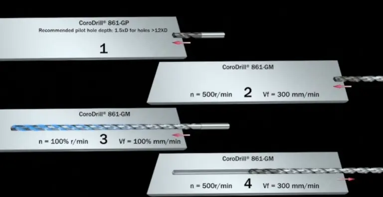
  2. Guide Drill: Accurately pierces a pilot hole (depth typically 1.5D-2D) on the pad. This pilot guides the subsequent deep hole drill and ensures initial alignment.
  3. Deep Hole Drill: Completes the full-depth oil passage using BTA, ejector, or dedicated gun drilling setups. Requires specialized coolant through-tool.
  4. Orifice Chamfer: Deburrs entry and exit points to remove dangerous metal fragments and ensure proper oil flow.

Critical Considerations:

  • Hole Types: Distinguish Cross Holes (intersecting connecting rod & main journal paths – complex) vs. Straight-Through Holes. Cross holes demand exceptional precision.
  • Avoid Combined Tools: Using a flat bottom drill with a center point (not recommended) might seem faster but drastically increases tool wear and cost. Dedicated pilot drilling is superior.
  • Tool Length Awareness: Pilot drills must be significantly shorter than their flat-bottom precursors to prevent collisions during retract.
  • Chamfer Consistency: New tools require depth/program adjustment to maintain consistent chamfer dimensions.
  • MQL / Coolant Health: Insufficient flow leads to drill seizure and part damage. Monitor consumption and pressure strictly.
  • Pre-Drill Check: Always verify coolant passages in deep hole drills are clear before installation.

Key Factors Influencing Success

1. Process Parameters

  • Rigidity & Alignment: Near-perfect coaxially from machine spindle > drill guide bushing > workpiece axis > support bushing is non-negotiable.
  • Thorough Hole Start: A true, perpendicular starting surface is imperative. Avoid drilling directly on angled or uneven features pre-flat bottom operation.
  • Cutting Edge Integrity: Maintain sharp edges for clean chip formation. Promptly replace worn guides and supports.
  • Pecking Strategy: Essential for chip control and heat dissipation in CNC operations.
  • Through-Hole Technique: Reduce feeds dramatically upon breakthrough (~last 1-2mm) to prevent tool tip fracture.

Cut Fluid Strategy

Coolant acts as lubricant, coolant and chip conveyor. Select based on application:

Cutting Fluid Type Best For Kinematic Viscosity & Notes
Soluble Oil Emulsion General deep hole drilling, good economics Balance cost & performance. Good lubrication/cooling
Extreme Pressure Emulsion Higher accuracy, difficult materials Higher film strength for demanding alloys/materials
Low-Viscosity Cutting Oil Small diameters (<6mm) ~10-20 cSt; Good penetration
High-Viscosity Cutting Oil Large diameters, high precision ~10-20 cSt; Better heat removal, surface finish
Special Blend (e.g., 40% Kerosene + 60% Chlorinated Paraffin) Critical precision applications Minimizes friction, optimizes accuracy; requires careful handling
  • Flowrate: Critical for flushing. Typical velocities: 15-18 m/s.
  • Pressure: Directly related to hole diameter and method. Higher for smaller holes/gun drilling.

Troubleshooting Deep Hole Drilling Defects

Poor Hole Surface Finish
Cause: Incorrect feed/speed, tool wear, coolant issues/failure, chatter.
Solution: Optimize parameters, guarantee tool sharpness, ensure adequate/correct coolant pressure & flow, enhance stability.

Tool Breakage Part 1
Cause: Chip jamming secondary to breakage.
Solution: Refine chip formation using optimal feeds/speeds, deploy pecking strategies, improve coolant delivery.

Tool Breakage Part 2
Cause: Jamming leading to overload breakage.
Solution: Guarantee chip conveyor efficiency (adequate flow/pressure), select geometry better suited to material, maintain proper coating/tool integrity.

Workpiece Damage
Cause: Collisions from poor clearance, chips marking walls.
Solution: Maintain tool support, optimize chip removal, utilize through-spindle coolant effectively.

Tool Tip Fracture
Cause: Feed rate way too high upon breakthrough.
Solution: Implement programmed feed rate reduction near hole exit.

Hole Taper
Cause: Tool deflection or uneven wear on guides/cutting edges.
Solution: Improve alignment/bearing condition, sharpen tool, confirm coolant effectiveness, check tool rigidity.

Axis Deviation
Cause: Misalignment, excessive tool side forces, insufficient support near exit.
Solution: Rigorous checks on machine/bushing/workpiece alignments (coaxially!), verify tool runout, optimize feeds/speeds.

Mastering deep hole drilling demands meticulous attention to process parameters, tooling integrity, robust coolant strategies, and unwavering process discipline. Applying these principles ensures the production of intricate, high-precision components like crankshaft oil passages remains efficient and reliable. Continuous monitoring and refinement are the hallmarks of successful deep hole operations in competitive manufacturing environments.

CNC Experts

Picture of JinShui Chen

JinShui Chen

Rapid Prototyping & Rapid Manufacturing Expert

Specialize in CNC machining, 3D printing, urethane casting, rapid tooling, injection molding, metal casting, sheet metal and extrusion

CNC Recent Posts

CNC News

Welcome to GreatLight Metal,Maximum Processing Size 4,000 mm

Precision Machining CNC Quote Online

Loading file

Upload Click here to upload or drag and drop your model to the canvas.

The model is too large and has been resized to fit in the printer's build tray. [Hide]

The model is too large to fit in the printer's build tray. [Hide]

The model is too large, a fitting printer is selected. [Hide]

The model is too small and has been upscaled. [Hide]

Warning: The selected printer can not print in full color [Hide]

Warning: obj models with multiple meshes are not yet supported [Hide]

Warning: Unsupported DXF entity  [Hide]

Warning: could not arrange models [Hide]


File Unit:      
Scale:
%
L × W × H:
X: × Y: × Z:  cm 
Rotation:
X: ° Y: °  

	
⚡ Instant Quote for Precision Manufacturing

Submit your design files (STEP/IGES/DWG) and receive a competitive quote within 1 hour, backed by ISO 9001-certified quality assurance.

📋 How It Works

  1. Upload & SpecifyShare your 3D model and select materials (Aluminum/Stainless Steel/Titanium/PEEK), tolerances (±0.002mm), and surface treatments.

  2. AI-Powered AnalysisOur system calculates optimal machining strategy and cost based on 10+ years of automotive/aerospace data.

  3. Review & ConfirmGet a detailed breakdown including:
    - Volume pricing tiers (1-10,000+ units)
    - Lead time (3-7 days standard)
    - DFM feedback for cost optimization

Unit Price: 

Loading price
5 Axis CNC Machining Equipment
4 Axis CNC Machining Equipment
3 Axis CNC Machining Equipment
CNC Milling & Turning Equipment
Prototype and Short-Run Injection Moldings Exact plastic material as final design
Volume Metal Die Casting Services - Precision Cast Parts
Bridge the Gap From Prototype to Production – Global delivery in 10 days or less
Custom high-precision sheet metal prototypes and parts, as fast as 5 days.
Custom Online 3D Printing Services
Design Best Processing Method According To 3D Drawings
Alloys Aluminum 6061, 6061-T6 Aluminum 2024 Aluminum 5052 Aluminum 5083 Aluminum 6063 Aluminum 6082 Aluminum 7075, 7075-T6 Aluminum ADC12 (A380)
Alloys Brass C27400 Brass C28000 Brass C36000
Alloys Stainless Steel SUS201 Stainless Steel SUS303 Stainless Steel SUS 304 Stainless Steel SUS316 Stainless Steel SUS316L Stainless Steel SUS420 Stainless Steel SUS430 Stainless Steel SUS431 Stainless Steel SUS440C Stainless Steel SUS630/17-4PH Stainless Steel AISI 304
Inconel718
Carbon Fiber
Tool Steel
Mold Steel
Alloys Titanium Alloy TA1 Titanium Alloy TA2 Titanium Alloy TC4/Ti-6Al 4V
Alloys Steel 1018, 1020, 1025, 1045, 1215, 4130, 4140, 4340, 5140, A36 Die steel Alloy steel Chisel tool steel Spring steel High speed steel Cold rolled steel Bearing steel SPCC
Alloys Copper C101(T2) Copper C103(T1) Copper C103(TU2) Copper C110(TU0) Beryllium Copper
Alloys Magnesium Alloy AZ31B Magnesium Alloy AZ91D
Low Carbon Steel
Alloys Magnesium Alloy AZ31B Magnesium Alloy AZ91D
ABS Beige(Natural) ABS Black ABS Black Antistatic ABS Milky White ABS+PC Black ABS+PC White
PC Black PC Transparent PC White PC Yellowish White PC+GF30 Black
PMMA Black PMMA Transparent PMMA White
PA(Nylon) Blue PA6 (Nylon)+GF15 Black PA6 (Nylon)+GF30 Black PA66 (Nylon) Beige(Natural) PA66 (Nylon) Black
PE Black PE White
PEEK Beige(Natural) PEEK Black
PP Black PP White PP+GF30 Black
HDPE Black HDPE White
HIPS Board White
LDPE White
This is a finish of applying powdered paint to the components and then baking it in an oven, which results in a stronger, more wear- and corrosion-resistant layer that is more durable than traditional painting methods.
No coating required, product’s natural color!
This is a finish of applying powdered paint to the components and then baking it in an oven, which results in a stronger, more wear- and corrosion-resistant layer that is more durable than traditional painting methods.
This finishing option with the shortest turnaround time. Parts have visible tool marks and potentially sharp edges and burrs, which can be removed upon request.
Sand blasting uses pressurized sand or other media to clean and texture the surface, creating a uniform, matte finish.
Polishing is the process of creating a smooth and shiny surface by rubbing it or by applying a chemical treatmen
A brushed finish creates a unidirectional satin texture, reducing the visibility of marks and scratches on the surface.
Anodizing increases corrosion resistance and wear properties, while allowing for color dyeing, ideal for aluminum parts.
Black oxide is a conversion coating that is used on steels to improve corrosion resistance and minimize light reflection.
Electroplating bonds a thin metal layer onto parts, improving wear resistance, corrosion resistance, and surface conductivity.
This is a finish of applying powdered paint to the components and then baking it in an oven, which results in a stronger, more wear- and corrosion-resistant layer that is more durable than traditional painting methods.
Please provide additional text description for other surface treatment requirements!
Material
Material
  • CNC Metals
    • Aluminum
    • Brass
    • Stainless steel
    • Inconel718
    • Carbon Fiber
    • Tool Steel
    • Mold Steel
    • Titanium
    • Alloy Steel
    • Copper
    • Bronze
    • Low Carbon Steel
    • Magnesium
  • CNC Plastics
    • ABS
    • PC
    • PMMA (Acrylic)
    • PA (Nylon)
    • PE
    • PEEK
    • PP
    • HDPE
    • HIPS
    • LDPE
Printer
Printer
  • CNC Metals
    • 5 Axis CNC Machining
    • 4 Axis CNC Machining
    • 3 Axis CNC Machining
    • CNC Milling & Turning
    • Rapid Tooling
    • Metal Die Casting
    • Vacuum Casting
    • Sheet Metal Fabrication
    • SLA 3D Printing
    • SLS 3D Printing
    • SLM 3D Printing
  • Rapid Prototyping
    • Design Best Processing Method According To 3D Drawings
Post-processing
Post-processing
  • As Machined(Product’s natural color)
  • Sand Blasting
  • Polishing
  • Brushed Finish
  • Anodizing
  • Black Oxide
  • Electroplating
  • Paint Coating
  • Powder Coating
  • Other surface treatment requirements
Finalize
The world's first CNC machining center that dares to provide free samples!

Free for first product valued at less than $200. (Background check required)

precision machining cnc quote online

15 Years CNC Machining Services

When you’re ready to start your next project, simply upload your 3D CAD design files, and our engineers will get back to you with a quote as soon as possible.
Scroll to Top

ISO 9001 Certificate

ISO 9001 is defined as the internationally recognized standard for Quality Management Systems (QMS). It is by far the most mature quality framework in the world. More than 1 million certificates were issued to organizations in 178 countries. ISO 9001 sets standards not only for the quality management system, but also for the overall management system. It helps organizations achieve success by improving customer satisfaction, employee motivation, and continuous improvement. * The ISO certificate is issued in the name of FS.com LIMITED and applied to all the products sold on FS website.

greatlight metal iso 9001 certification successfully renewed
GB T 19001-2016 IS09001-2015
✅ iso 9001:2015
greatlight metal iso 9001 certification successfully renewed zh

IATF 16949 certificate

IATF 16949 is an internationally recognized Quality Management System (QMS) standard specifically for the automotive industry and engine hardware parts production quality management system certification. It is based on ISO 9001 and adds specific requirements related to the production and service of automotive and engine hardware parts. Its goal is to improve quality, streamline processes, and reduce variation and waste in the automotive and engine hardware parts supply chain.

automotive industry quality management system certification 01
Certification of Production Quality Management System for Engine Hardware Parts Engine Hardware Associated Parts
automotive industry quality management system certification 00
发动机五金零配件的生产质量管理体系认证

ISO 27001 certificate

ISO/IEC 27001 is an international standard for managing and processing information security. This standard is jointly developed by the International Organization for Standardization (ISO) and the International Electrotechnical Commission (IEC). It sets out requirements for establishing, implementing, maintaining, and continually improving an information security management system (ISMS). Ensuring the confidentiality, integrity, and availability of organizational information assets, obtaining an ISO 27001 certificate means that the enterprise has passed the audit conducted by a certification body, proving that its information security management system has met the requirements of the international standard.

greatlight metal technology co., ltd has obtained multiple certifications (1)
greatlight metal technology co., ltd has obtained multiple certifications (2)

ISO 13485 certificate

ISO 13485 is an internationally recognized standard for Quality Management Systems (QMS) specifically tailored for the medical device industry. It outlines the requirements for organizations involved in the design, development, production, installation, and servicing of medical devices, ensuring they consistently meet regulatory requirements and customer needs. Essentially, it's a framework for medical device companies to build and maintain robust QMS processes, ultimately enhancing patient safety and device quality.

greatlight metal technology co., ltd has obtained multiple certifications (3)
greatlight metal technology co., ltd has obtained multiple certifications (4)

Get The Best Price

Send drawings and detailed requirements via Email:info@glcncmachining.com
Or Fill Out The Contact Form Below:

All uploads are secure and confidential.