
Advantages of High Precision Valve Seat CNC Machining
A valve seat is a sealing surface before it is a part. The seat angle, concentricity, and finish decide whether the valve shuts off at pressure. This page explains what 5-axis CNC machining controls on valve seats, which materials and geometries it suits, and the cases where it is the wrong process. Written for design engineers, process engineers, and buyers who sign off on the drawing.
What the advantages actually are
Seat angle, seat width, and concentricity to the guide bore drive sealing. Everything else is support work.
What the advantages of high precision valve
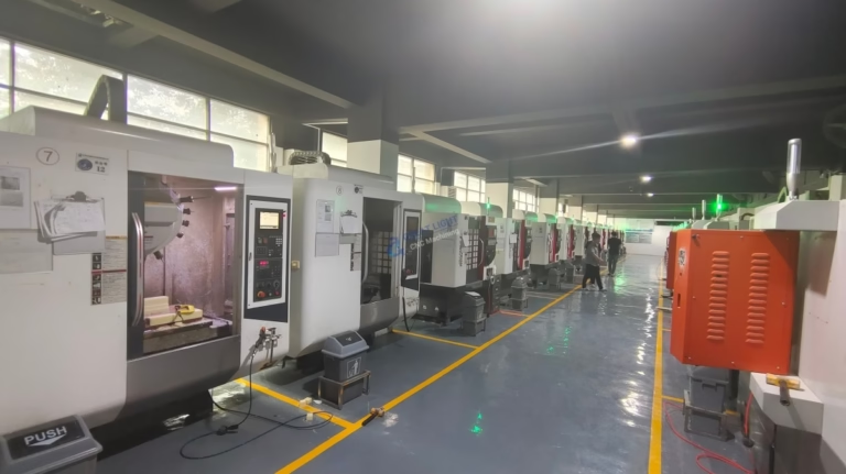
Valve seats fail for three reasons: the seat angle drifts, the seat runs off-center to the guide bore, or the sealing face is too rough to bed in. High precision valve seat CNC machining addresses all three in one setup. On a 5-axis machine, the seat face, the guide bore, and the mounting flange are cut without re-fixturing, so the angular relationship between them stays inside ±0.005 mm. That number matters because a 0.01 mm eccentricity on a 45° seat can open a leak path that no spring pressure closes.
Seat width is the second control point. Too narrow, and the seat pounds itself into the valve head under repeated cycling. Too wide, and contact pressure drops below what is needed to crush contaminants. A CNC program holds seat width to a band instead of a nominal, which is what allows a production run to pass a leak test at the end of the line rather than being sorted by hand.
The third advantage is repeatability across a run. Once the tool path, tool wear offsets, and thermal compensation are dialed in, part 1 and part 5,000 come off the same. For a valve seat, batch consistency is often worth more than the tightest single-part tolerance, because a seat that seals in the test rig but not in the field is a warranty claim.
- 1One setup, three featuresSeat, guide bore, and flange cut in the same fixturing to protect concentricity.
- 2Seat width held to a bandContact pressure stays predictable instead of drifting with tool wear.
- 3Run-to-run repeatabilityWear offsets and thermal compensation keep part 1 and part 5,000 aligned.
Surface finish on the sealing face
Finish is not cosmetic here. A seat face at Ra 1.6–3.2 μm will seal, but it needs a longer bedding cycle and it holds more debris in the valleys. Pulling the face to Ra 0.8–1.6 μm shortens bedding and reduces the chance of a slow weep. For hydraulic and high-pressure gas seats, we run to Ra 0.2–0.8 μm, which usually means a fine boring pass followed by a light lapping or a burnishing tool, depending on the material.
The catch is that finer finish costs cycle time and demands a stiffer setup. A long, slender seat body will chatter before it reaches Ra 0.4 μm, no matter how sharp the insert is. When that happens, the honest answer is to change the geometry or add a support, not to keep chasing the number.
Direction of the tool marks also matters. A seat face with a controlled circular lay seals differently from one with a crosshatch, and some OEM specs call out the lay explicitly. We program the finishing pass to match the drawing rather than letting the CAM default decide.
Matching material to the seat duty
Material choice decides how the seat wears. A soft seat in a hard body deforms to seal and tolerates light contamination, which is why brass and bronze seats appear in low-pressure water and air valves. A hard seat in a hard body resists erosion and high temperature, but it needs a better finish and cleaner fluid to seal reliably.
Stainless grades are common where corrosion matters. We machine 303, 304, 316, 316L, 420, 430, 431, 440C, and 17-4PH (SUS630). The 400-series and 17-4PH can be hardened after machining, so the seat face is cut in the annealed state and then heat treated. That sequence changes the finishing allowance, so the drawing should state the final hardness and the heat-treat step up front.
For high-temperature exhaust and turbine service, Inconel and titanium (TA1, TA2, TC4) show up. Both are abrasive and prone to work hardening. They cut cleanly on a rigid 5-axis center with the right insert grade, but they punish light finishing passes and slow the cycle. If a seat does not need the temperature capability, 17-4PH usually gets the job done at lower cost.
Seat material and finish by duty
Starting points, not fixed rules. Confirm against the drawing and the fluid.
| Seat material | Typical duty | Target seat finish | Notes |
|---|---|---|---|
| Brass C36000 | Low-pressure water and air | Ra 1.6–3.2 μm | Soft seat deforms to seal |
| Stainless 316L | Corrosive media, moderate pressure | Ra 0.8–1.6 μm | Cut before or after passivation |
| 17-4PH (SUS630) | Hydraulic, high pressure | Ra 0.2–0.8 μm | Machine annealed, then heat treat |
| 440C | Hard seat, erosion resistance | Ra 0.2–0.8 μm | Finish allowance set before hardening |
| Inconel | High-temperature exhaust | Ra 0.8–1.6 μm | Abrasive, slower cycle, rigid setup |
| TC4 (Ti-6Al-4V) | Aerospace, weight-critical | Ra 0.2–0.8 μm | Work hardens, avoid light passes |
When CNC machining is not the right fit
A CNC-machined seat is the wrong answer when the seat is a hardened insert pressed into a body. In that case the insert is ground and lapped, and the accuracy comes from the grinding spindle, not from milling. We can machine the pocket to hold the insert, but the seat surface itself belongs to a grinder.
Another limit is quantity. For tens of thousands of small seats in a single geometry, a die-casting or forging process with a machining pass on the seat face may cost less per part. CNC earns its place when the geometry is complex, the batch is mixed, or the lead time is short. With no minimum order quantity, we run from one prototype to 10,000+ part runs, and the seat face is cut the same way in both cases.
Finally, if the drawing calls for a seat angle tighter than ±0.005 mm or a finish below Ra 0.2 μm, that is a grinding or lapping operation. Sending it to a mill just moves the problem downstream. We would rather flag that during DFM than ship a part that passes inspection and weeps in service.
Questions engineers ask
What tolerance can you hold on a valve seat face?
We hold ±0.005 mm (±0.0002 in) on seat geometry and concentricity to the guide bore. The practical limit depends on the part's aspect ratio. Short, well-supported seats hold the tight end of that band. Long slender seats need a support or a geometry change.
The drawing should state which feature is the datum. If the guide bore is the datum, we cut from the bore. If the mounting flange is the datum, the seat runs to that instead. The two give different results.
How fine a surface finish can you produce on the seat?
We machine down to Ra 0.2–0.8 μm on suitable parts. A fine boring pass gets to Ra 0.8–1.6 μm reliably, and a light lapping or burnishing step takes it lower.
Below Ra 0.2 μm becomes a grinding or lapping operation. We will tell you during DFM if your target sits past what a mill can hold on your part.
Do you machine hardened valve seat materials?
Yes, up to a point. 420, 431, 440C, and 17-4PH are usually machined in the annealed or pre-hardened state, then heat treated. The finishing allowance is set before the heat-treat step so the seat face lands on size afterward.
Full-hard material above roughly 45 HRC is a grinding job. We machine the surrounding features and leave the seat face to a grinder.
Can you cut the seat and the guide bore in one setup?
That is the main reason to use a 5-axis center for this work. Both features are cut without re-fixturing, which keeps the angular relationship and the concentricity under control.
On a 3-axis machine, the same part needs two setups and a re-datum between them. The added stack-up usually eats most of the tolerance budget.
What does DFM feedback cover for a valve seat part?
We look at seat angle and width, datum choice, wall thickness around the seat, thread and port locations, and whether the finish target is reachable in the chosen material. You get the quotation and a free DFM analysis within 12 hours.
If a feature should be ground rather than milled, that shows up in the DFM notes before you commit to a run.
How do you keep seat quality consistent across a production run?
Raw material is checked on receipt. In-process monitoring tracks tool wear and dimensional drift, and offsets are updated before the seat face moves out of band. Final inspection runs on 100% of parts before shipment, with reports available on request.
Our historical qualification rate is 99.99%, and the historical late-delivery probability is below 2%.
Send the seat drawing and get a real answer
Quotation and free DFM analysis within 12 hours. No minimum order quantity, from one prototype to 10,000+ parts.
12-hour quote±0.005 mm tolerance100% inspectionNDA on request









