1 overview
In recent years, my country’s national economy has grown quickly. The machine plays a crucial role there. A shield speed reduction is a reduction transmission device between the shield mechanism and a driving engine or a hydraulic motor. The central gear reduction of the shield machine drive mainly includes the main drive reducer of the cutting plate, the screw conveyor reducer and the reducer of the entire pipe sheet.
The reducer of the shield machine equipment is a small and medium -sized planetary speed device with high power density. Its working conditions are characterized by: continuous work, variable speed, variable load, poor working conditions, accompanied by certain impact charges and great reliability. This chapter will introduce the structural characteristics of the forms of transmission commonly used for shielding equipment reducers, and the content is reserved for design.
Main training reducer of the cutting plate
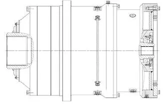
The main drive reducer of the knife wheel is mainly used to transmit the torque and control the rotation speed to drive the cutting wheel of the shield machine. It is generally synchronously driven by several planetary reducers of the same specification, and its transmission ratio is mainly in the I = 15 ~ 200 range, and adopts a planetary structure with two floors or three stages. The reducer is divided at the outlet of the spline and the cerebridge door shaft as a function of the output shape.
This series of reducers is generally made up of water cooling devices and NGW planetary speed devices. Some main training reducers are designed with brakes at the entry end.
The main characteristics of the main main reduction design above are:
Due to the limited installation and the space of use and the poor heat dissipation capacity of the main driver, a large amount of heat will be generated during long -term use. of the reducer to increase sharply, which will affect the lubrication of the performance of the reducer; Breakdown film, causing a breakdown of thermal glue on the surface of the tooth and the surface of the port, and ultimately causes a failure of the reducer. It is crucial to design a high -reliability continuous circulation cooling device to solve the thermal balance and control of the temperature. This series of reducers adopts a design of cooling water reservoir integrated at the end at high speed input, which removes heat generated inside the reducer through the cooling water in circulation, thus reaching The thermal dissipation function.
(a) Pressure under the cooling water tank must be 0.5 to 1 MPa, and no leaks are allowed. It is recommended to use the welded or integrated flow box, pay attention to the control of welding and casting defects; The box must undergo a sealing pressure test, the pressure is controlled at 0.5 ~ 1MPA and the pressure outfit is 60 to 120 minutes.
(b) The calculation of the thermal power of the reducer is based on the GB / T33923 standard; Since the reducer cooling water is connected in series with the engine water circuit, the flow and temperature involved in the cooling calculation of the whole system must be fully paired. The heat exchange area inside the cooling box will determine its specific structure to some extent.
(c) In order to meet the high needs of corrosion and rust, it is recommended to use the paint coating and other technologies;
(d) The potential failure points of the cooling water tank must be arranged at the outer end of the gearbox as much as possible to avoid direct contact with cooling water with the lubricant after leakage ; To consider an interface to monitor cooling water leaks for an easy time inspection.
(2) Selection of equipment settings
In order to improve the reducer power density, the planetary wheels system often adopts a 3-4 diversion, a low-speed stage, a low-speed ratio and a large modular design. The solar speed and the planetary wheel are made of steel in a low carbon, carbureated and extinguished alloy, with a dental surface hardness of 58 ~ 62hrc, a central hardness of 30 ~ 42hrc, and a crushing of dental surface reaches the 5th or the 6th year of GB / T10095; The form and orientation of the planetary wheel and the solar gear can reduce the coefficient of distribution of the tooth load to a certain extent, avoiding the concentration of constraint caused by the biased load;
(3) Rolling configuration
To meet the variable load conditions, high -speed planetary speed wheels are recommended to be equipped with roller bearings with cages to avoid the undesirable effects of the high -speed planetary gear as possible; The speed of rotation is low and the planetary gear bearings are arranged, the space is seriously limited, and it is generally equipped with high load loads, not full loading bearings. The diamond coating methods, which can solve the problem of the shift of the rolling elements in loading conditions and the difficulty of forming the film in lubricating oil at low speed further reduces the risk of wear of the rolling elements and prolonged the lifespan of the rolling; The planetary wheel as an external race course has high precision requirements, and the hardness of the interior bore racing path is ≥58hrc.
(4) Floating mechanism and axial authorization
High -speed planetary notes and intermediate planetary assessments generally use solar equipment and planet carrier to float at the same time, while low -speed planetary dimensions use solar gear to float. A floating mechanism with a load is adopted and its floating parts must have sufficient axial clearance.
(5) Lubrication of the reducer
The main reducer is generally installed horizontally and is lubricated with oil immersion. The highest and lowest oil level line.
3 screws carrying a reducer
The spiral transport reducer is responsible for transporting the soil and the stone to the outside to ensure a smooth excavation of the front cut plate. Its transmission ratio is mainly located in the range of I = 3 ~ 100, and involves four structures: gear reducer parallel to a stage, planetary speed reducer of the first step, planetary speed reducer and speed reduction third floor planetary. Depending on the structural form, reducers are mainly divided into two categories: the planetary level NGW and the multi-light parallel level.
The main characteristics of the spiral reducer design above are:
(1) Selection of equipment settings
Reducing planetary wheel trains of the planetary spiral transmitting planetary wheel trains often use a transmission of diversion from 3 to 4; The Multi-Greffe Multi-Greffe parallel transfer gable uses 2 to 3 transmission of the crowd. The gears are made of low carbon, carburetor and extinguished alloy steel, with a dental surface hardness of 58 ~ 62hrc, a central hardness of 30 ~ 42hrc and a dental surface grinding reaches 5 or 6 levels of GB / T10095 ; To improve the bending resistance of dental root and tooth, the roots are reinforced.
(2) Rolling configuration
The installation angle of the reducing reducer of the screw conveyor and the horizontal line are generally 20 to 25 °. The diameters during the inclined installation.
(3) extreme pressure bearing
In order to prevent the shield machine from going backwards and water from damaging the reducer and other key equipment, the reducer output seal requires an extreme pressure of 1 MPa. Design and select materials, customize dimensional structures and combined forms according to the requirements of mud and water environment, pressure, etc.
(4) Lubrication of the reducer
The screw revocat is generally installed horizontally with an inclination of 20 to 25 ° and is lubricated with the oil. And the minimum oil level must be guaranteed to have entered the joint and complete lubrication of the bearings.
4 assembly sheet pipes
Usually, it is supported by rotation by pipes of pipes assembled to the assembly machine of reductive driving pipes, and finally ends the assembly task of lining pipe sheets; It also has a locking function. Its transmission ratio is mainly in the range of I = 15 ~ 50, and is mainly composed of friction plate brakes and planetary gear structures with two floors.
The main characteristics of the design of the reducer of the pipe set are:
(1) Braking design
The input terminal has a friction pad brake, which is generally designed as a normally closed type, that is to say that high pressure oil is not provided, the brake is in a state of tight locking, which can be used for static braking; And during the normal operation of the reducer, it must be opened continuously. The Safety Factor of the Brake Fritation Flat Torque Transfer Design is Recommended ≥1.2, and the Safety Factor of the Flat Discange Design is Recommended ≥1.5, and the Total Gap of the Flat Disengalement is Recommended ≥0.3x2xa (A-Number of friction plates); The specific design is referenced to JB / T 9713. CB / T 3454 and other standards.
(2) Adjustment of eccentricity
In order to facilitate the precise adjustment of the space between the reducer output gear and the equipment of the rotary support cycle, the output flange and the output equipment adopt an eccentric design, and the eccentric distance is generally 1 , 5 to 2.5 mm.
(3) Rolling configuration
All components of the reducer are generally supported by rolling bearings. The planetary wheels use rolls with needle rollers or rollers, and most of the overhang output gears are supported by centripet or conical roller bearings.
(4) Lubrication of the reducer
The reducer is installed horizontally, using oil lubrication, and generally uses fully synthetic industrial speed of 150-220; To adjust the installation oil when the installation angle of the reducer changes.
Daguang focuses on providing solutions such as precision CNC machining services (3-axis, 4-axis, 5-axis machining), CNC milling, 3D printing and rapid prototyping services.


