(1) The reference
The parts are made up of several surfaces and each surface has a certain size and mutual position requirements. The relative position requirements between the surface of the parts include two aspects: the precision of the size of the distance and the precision of the relative position of the surface requirements (such as the axis, the parallelism, the verticality and the round jump). The relative position relationship between the surface of the parts is inseparable from the reference, and the position of the parts cannot be determined without clearly the reference. In terms of general meaning, the points, lines and plans based on the positions of other points, lines and faces are used on the parts. The benchmarks can be divided into two categories: the design benchmark and the process reference according to their effects.
1. Reference design
It is used to determine the landmarks of other points, lines and planes on the parts diagram. the sales hole.
2. Artisanal benchmark
The reference used in the processing and assembly process is called the reference process. The reference of the process is divided with positioning reference, measurement reference and assembly reference according to the different uses.
(1) Benchmark positioning: During treatment, the reference for parts to occupy the correct position in the machine tool or the light, which is called positioning reference. Depending on the different positioning elements, the most commonly used are the following two categories:
Automatic positioning of care: such as the positioning of the card with three claws.
Positioning of positioning positioning: Transform the positioning element in a positioning set, such as stopping the oral positioning positioning
Others are positioned in the V-shaped frame, positioning in the semi-circular hole, etc.
(2) Measurement benchmark: When the part is inspected, it is used to measure the base and the position of the size and position of the treated surface, which is called measurement reference.
(3) Benchmark architecture: The reference to determine the position of the part in the component or the product during the assembly is called assembly reference.
(2) The parts installation method
In order to process the surface which meets the technical requirements prescribed to a certain part of the part, before the mechanical treatment, the part must be used to occupy a certain correct position on the machine tool. This process is generally called “positioning” of the parts. After the positioning of the room, due to the role of the cutting force and the severity during the treatment, a certain institution must also be used to “tighten” the part to maintain the determined position unchanged. The part activation process to occupy the correct position on the machine and tighten the part as “installation”.
Installing parts is an important problem in mechanical treatment. In order to guarantee the accuracy of the relative position between the processing surface and its design reference, the design reference on the processing surface must be used to occupy a correct position when installing the part. For example, in order to guarantee the requirements of round sauce of the lower diameter of the ring groove and the axis of the skirt, the design reference must be reunited with the axis of the main axis of the machine- tool during installation.
There are different installation methods when processing parts on various machine tools. The installation method can be summarized as three types of research directly Orthodox, line lines and use of the lighting installation methods.
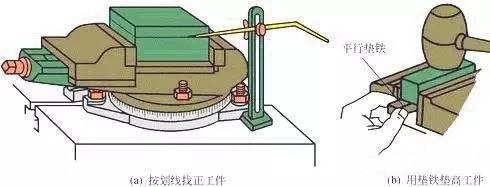
(1) When you use this method directly in FA reflection, the correct position that the part must occupy on the machine tool is obtained by a series of attempts. The specific method consists in putting the part directly on the machine tool and using the needle of the table as a percentage or the race to draw a needle to visually check the correct position of the part and check the positive appearance until to what he meets the requirements.
Find the positioning precision of the FA re-notification and the rapid and the slowdown in the law and slow, according to the technical level of the search for positive precision, to find a correct method, to find the tools and the workers. Its disadvantages are that it costs more time, low productivity and requires high requirements for workers technology according to experience. If the justice of imitation of the form is in search of Dharma directly.
(2) The search for the Dharma line is a method to find the part with the lines drawn by the rough or semi-finished product on the machine tool to obtain the correct position. Obviously, this method must be more line. The patterns have a certain width, and there is a line error when the line is drawn. For example, determining the position of the nail hole in two cases is to use the cutting -edge line method to find positive.
(3) Use the luminaire installation method: it is used to install clip parts to make the process equipment that has the correct position as a machine-tool lighting. The luminaire is an additional device of the machine tool. Our current piston treatment is the installation method of the lighting used.
1) After positioning the part, it is called tightening operations which maintain the unchanged positioning position during the processing process. In the luminaire, the device that keeps the part in the positioning positioning process is called a tightening device.
2) The tightening device must meet the following requirements: during tightening, the positioning of the part must not be destroyed; ; Rapid movement, operation and practical effort; Simple structure and easy manufacturing.
3) Precautions during tightening: The size of the tightening force must be appropriate, and the part deforms the part.

(3) Basic knowledge of metal cutting
1. The surface of the exercise and the race training
Driving exercise: During the cutting process, in order to remove excessive metals, the part and the tool must be relating to the cutting exercise.
Main movement: Direct cut on the cutting layer on the part to transform it into dandruff, thus forming a new surface movement on the room, called the main movement. During the cut, the rotation movement of the part is the main movement. Generally, the main movement is high and the cutting power consumed is larger.
Improvement movement: The new cutting layer is continuously in the cutting movement. For example, if the car knife is carried out continuously, the movement movement of the room on the bull’s plan is an intermittent movement.
The surface formed on the part: during the cutting process, the treatment surface, the treatment surface and the treatment surface of the treatment are formed on the part. The processed surface refers to the new surface formed by excess metal. The treatment surface refers to the surface of the metal layer which is about to be cut. The treatment surface refers to the surface where the cutting blade of the car knife is cut.
2. The three cutting elements refer to the cutting depth, power supply and cutting speed.
(1) Cutting depth: AP = (DW-DM) / 2 (mm) DW = diamond DM = diamond in the treatment room is diameter, and the cutting depth is what we usually call a knife.
Selection of the cutting depth: the αP cutting depth must be determined according to the treatment waste. During approximate treatment, in addition to leaving the balance of precision treatment, you must take the knife as much as possible to eliminate all rough treatment waste. This can not only do the cutting depth of the cut, power supply and cut speed V under the premise to ensure a certain durability, but also to reduce the number of times of the knife. In the case of insufficient excessive treatment or rigidity of the insufficient blade or resistance system, it must be divided in more than twice. At this time, the depth of the first sword must be greater, which may explain 2/3 to 3/4 of the total balance; and high treatment accuracy.
When the surface layer of the cutting parts has hard skin, forging or stainless steel, such as cold and hard and severe materials such as stainless steel, the cutting depth should exceed the hardness or the hard cold layer To avoid cutting the blades on the hard or cold hard layer skin.
(2) Selection of the power supply: the relative displacement of the part and the tools in the direction of the movement in the direction of the input of the tools and the tools is MM. Once the depth of the cut is selected, you should try to choose a larger amount of flow. The selection of the reasonable value of the supply volume should guarantee that the tool-tool and the tool are not damaged due to the too large cutting force, and that the deviation of the part caused by the cutting force does not Do not exceed the values authorized by the precision of the part and the parameters of surface roughness are not too important. During approximate treatment, the main thing is that the main one is the cut force, the treatment of semi-prision and precision treatment, the main surface roughness is mainly limited.
(3) Selection of cutting speed: During the cutting process, a certain point on the cutting blade of the tool is compared to the instantaneous speed of the main movement towards the surface of the process, and the unit is m / min. After the cutting depth of the cut depth of αp and the power supply ƒ, the maximum cutting speed is selected on the basis of a certain base.

(4) The concept of the roughness of mechanical science
In mechanics, roughness refers to the small geometric characteristics of the small spacing and micro-geometry composed of the Pic valley. This is one of the questions of interchangeability research. Surface roughness is generally formed by treatment methods and other factors used. the process system. Due to the different treatment methods and room materials, depth, density, shape and texture of the marks left by the treatment surface are different. Surface roughness is closely linked to complexity, resistance to abrasion, resistance to fatigue, the rigidity of contacts, vibrations and the noise of mechanical parts, which has a significant impact on the duration of life and reliability of mechanical products.
Roughness
Once the surface of the room was treated, it looks smooth, but it is uneven after enlarging the observation. The surface surface essence refers to the micro-geometry characteristics composed of a smaller spacing and a micro-peak valley on the surface of the treatment parts. The function of the parts is different and the values of the parameters of the required surface roughness are different. Surface roughness (symbol) must be marked on the room diagram to illustrate the surface characteristics which must be obtained once the surface is over. There are 3 types of surface roughness height parameters:
1. The average difference in the contour calculation is RA
In the sampling length, the average of the absolute values between the point between the outline and the reference line along the outline of the measurement direction (direction Y).
2. Uneven microphone at 10 hours RZ height
Referring to the sum of the average value of 5 peaks of maximum outline in the sampling length and the average value of 5 depth of maximum outline.
3. The maximum height of the Ry contour
In the sampling length, the distance between the upper line of the outline and the lowest bottom line.
Currently, the RA is mainly selected in the general machine industry.

4 Method of roughness representation

5. The effect of roughness on the performance of the parts
The surface quality of the part directly affects the physical, chemical and mechanical properties of the treated parts. In general, the surface quality requirements of large or key parts are higher than those of ordinary parts.
6. Cut liquid
(1) The role of the cutting fluid
Cooling effect: The thermal cutting energy removes a large amount of cutting heat, improves heat dissipation conditions, reduces the temperature of the tool and part, thus extending the lifespan of the tool and preventing size errors caused by the thermal deformation of the part.
Lubrication: The cutting fluid can penetrate between the room and the tool, so that a thin adsorption film forms in the small gap between the dandruff and the tool, which reduces the coefficient of friction. The wear of the tool and improves the quality of the room.
Cleaning function: the tiny crumbs generated during the cleaning process are easily adhered to the room and tools, especially when drilling deep holes and joint holes, crumbs are easily blocked in crumbs, which affects the Part surface roughness and the lifespan of the lifespan of the use of tools by the tool. The use of a cutting solution can quickly eliminate the dandruff and the cut takes place smoothly.
(2) Category: There are two categories of cutting liquids commonly used
Emulsion solution: It is mainly cooling. Tools and parts to improve the lifespan of the tool and reduce thermal deformation. The emulsion solution is more water and the lubrication and foreigner function is bad.
Cutting oil: The main component of cutting oil is mineral oil.
Daguang focuses on providing solutions such as precision CNC machining services (3-axis, 4-axis, 5-axis machining), CNC milling, 3D printing and rapid prototyping services.


