1 Preface
Under the development trend of vigorously developing advanced manufacturing and transforming and improving traditional industries, the structure of mechanical parts will inevitably develop in a more complicated and precise direction. Alien threads are widely used in the connection between connection equipment, ships, aerospace and other industries. Due to the large cutting force, the technical skills are high, the roughness of the processing surface is not suitable for processing large-shaped threads with high guidelines or high precision, and it is difficult to effectively control in quality terms. The method of using manual compilation macro program has greatly improved the accuracy compared with the training knife, but its characteristic is that the use of mathematical geometric formula instructions to control the tool processing path, but the difficulty of preparing High macro programming and thread section data need to be converted into a CNC processing program with complex logic judgment. In response to the above deficiencies, through active exploration and bold innovation, a method of using CAM software to use CAM software to cut off alien threads.
2 Technical analysis and difficulty
2.1 Analysis of extraterrestrial thread tooth shape
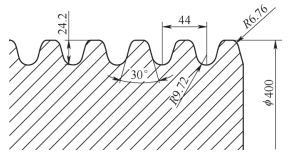
Circular cable-shaped wire (see Figure 1) The wire distance is 44mm, the tooth height is 0.55p = 24.2mm, the wire is 400mm, the upper arc of the top tooth R1 = 6.76mm, the lower arc R2=9.72MM, the tooth shape and circle threads and trapezoids are the same, both are 30°, and the wire contact height is between the round wire and the trapezoid wire. When processing programming, you need to use a knife arc to approach the part contributions node to calculate the shape curve of the knife arc to eliminate the adjustment part.
Figure 1 Trapezoidal Circular Wire Specification
Threaded sagon (see figure 2) The distance of the separator is 10 mm, the tooth height is 0.575p = 5.75 mm, the thread is 300 mm large diameter, the roof arch R1 = 0.75 mm , the lower arc R2 = 1.24mm, after the wire Rotation, after the screw rotation, after the screw rotation, the large diameter is not practical, and the dental corner is of 45°. single-way stress.

Figure 2 Sawtooth thread signal
During the processing method of large guide thread, the method of previous adjustment and then gradual cutting is adopted. Change the thread cycle through program control. -Shaped section.

Figure 3 Specification of trapezoidal wire layered car
2.2 Design of the processing tool
(1) The efficiency and surface quality of the tool selection of the tool depends on the selection of the threading knife specifications. If the normal thread processing method is adopted, large tool processing is selected. lead to deformation of the part and increase wear of the machine transmission. Select the knife in the knife along the wire contour line, which will greatly reduce the cutting resistance. Generally, the following points are considered a wire knife.
1) The matching of the shape of the thread tooth and the shape of the tool.
2) The tool width and r angle should be smaller than the smallest section size of the bottom of the thread.
3) Whether the blade material can meet the processing performance of the cut material.
4) Whether the tool can establish a practical operation logic relationship with the shape of the thread section.
(2) The design of the knife route design is the movement trajectory of the knife relative to the processing workpiece during lathe processing. Among the parts, its design is reasonable. Although the step distance reduction method can improve the surface roughness and precision to a certain extent, it will prolong the processing time and reduce the processing efficiency. In order to take into account precision and efficiency, the tool can process the workpiece in different feeding methods. Material, blade groove and thread distance. At present, there are three types of feeding methods: side-facing feeding method, radial feeding fertility and alternate feeding method. Determine the following principles in general.
1) Select the appropriate cutting rhythm to ensure the precision of workpiece processing parts.
2) Rotate the knife path and reduce the excess knife time.
3) Convenient value calculation, reduced programming difficulty and easy to check wrong points.
4) Control the number of segments and reduce the burden of machine reading.
2.3 Design of the alien thread processing program
Alien Cross section wire has a variety of tooth shapes. The alien wire is basically a large curved threaded screw, and the cutting force of the tools to generate the workpiece is not easy to master. The processing tool is usually an arc tank knife. The main idea is to use the NX 3D programming function to collect the coordinate point of the alien thread section, and through scientific replacement and verification, the process of finally obtaining the filming processing is finally achieved . The development process of the alien thread program is shown in Figure 4.

Figure 4 Alien thread program development process
3 Development implementation process
The thread program developed by this scheme successfully processed the trapezoidal threads, sawtooth threads and trapezoidal threads mentioned above. It should be noted that this method is also applicable to processing rectangular and conical threads (parabolic, bilateral), etc. The following analysis is the method to create the TY400X44 trapezoidal thread processing program.
3.1 Determine the thread section
TY400X44 thread (see figure 5) The thread distance is 44mm, the tooth height is 0.55p=24.2mm, the thread is 400mm, the upper arc of the top of the tooth R1=6, 76 mm, the lower arc R2 = 9.72 mm,![]() Essence The theoretical contour section data is obtained according to the GB/T 10051.5-2010 standard, and the CAD is drawn by 1:1. When processing programming, you need to calculate the contour node of the parts, from so that the knife arc is cut to cut the shape curved surface of the fittings to ensure the surface roughness value RA=3.2μm and the tolerance to the wire.
Essence The theoretical contour section data is obtained according to the GB/T 10051.5-2010 standard, and the CAD is drawn by 1:1. When processing programming, you need to calculate the contour node of the parts, from so that the knife arc is cut to cut the shape curved surface of the fittings to ensure the surface roughness value RA=3.2μm and the tolerance to the wire.

Figure 5 Section TY400X44 Thread Basic
3.2 Cutter Cutting Analysis
The 8mm wide groove knife is used to enter the knife in turn along the contour line of the wire, as shown in Figure 6, which will greatly reduce the cutting resistance. Use CAM programming to use a threaded knife to ensure the following points: ① The knife head crumbs should be smooth. ② The width of the knife and the angle R should be smaller than the smallest section size of the bottom of the thread. ③ Whether the blade material can meet the processing performance of the cut material. ④ Software knife library settings correspond to the actual threaded knife.

Figure 6 Analysis of knives and threading tooth shape
3.3 QR Data Import NX 3D SOFTWARE
After confirming the erroneous two-dimensional contour, it needs to be converted into a three-dimensional model, and the specific operation is as follows.
Open the NX software.
3.4 Descartes coordinate parameters
Threads are usually set on the theoretical axis on CNC machines. , then the XM+ facing the wire is rounded, then the ZM+ facing the screw end surface, as shown in Figure 7.

Figure 7 Coordinate system settings
The processing module entry must also define the processing coordinate system. The y value does not exist in the lap coordinate system, and it exists in the map coordinate system. Later use of the milling thread section function will be used, but it will ultimately be omitted when transitioning from the program to the turning process.
3.5 Make the milling processing knife route
(1) Create a rugged single tooth outline[1]Only curved data of a tooth is required in the following tracking settings settings. The operation steps are as follows: Enter the sketch → draw the stretch area line box → Select the stretch command → Select the stretch outline → The stretch thickness is 5mm → Confirm . The creation model is shown in Figure 8.

Figure 8 Create a template
(2) specify the processing method[2] By entering the processing application module, it can provide functions such as interactive programming and post-procedure. The main idea of this processing scheme is to convert the knife path trajectory generated by NX to powerful milling functions to complete the processing of alien wire. The selected processing method is mill outline subprocess, and the subtype is Cavity_mill. Because it can accurately control the tool rules and clearly until grinding, it is especially suitable for the rough car knife path for the large time-shaped threaded wire.
(3) Enter the specifications of the tool specifications and enter the selected tool specifications in the parameter table. can be improved for a long time.
(4) Select the curved contour that needs to be processed in the digital mold created by the cutting area. Enter the sketch interface to draw the frame that needs to be cut. path of the knife. In order to increase the accuracy of the generation program, the internal and external tolerance options in the cutting parameter should be set to 0.01 mm.
(5) Adjust the processing vector of the knife shaft. The intention of the carteial coordinate parameters, i.e. to facilitate the X value generators of the program can be directly used in the lathe processing coordinate system.
(6) DAO route trace parameters[3] This parameter is the most critical in the production of grinding and knife path processing. Set the maximum step distance to a constant 6mm, the cutting mode is one way, the depth of the public cutting depth of each knife is 0.1mm.
3.6 Generate simulation grinding and cutting knife route
After the previous round of preparation, generate a simulation knife path in the operation module. the path of the lower knife. If the knife path cutting trajectory and parameters are found during checking, the setting should be adjusted again.

Figure 9 Simulation Grinding Knife Route
3.7 Post-procedure export program
Export confirmed knife path as processing program. The general program header uses CNC G code instructions to define basic instructions such as knives, coordinate start, and speed walk knives.
3.8 Format and verification of the replacement program
Because it is generated by the die machine processing program, it cannot be used in CNC lathe processing, so the G code of the program needs to be replaced for the program to apply to processing towers. The specific operation steps are as follows. Replacement and verification of the thread program is shown in Figure 10

Figure 10 Thread Program Replacement and Verification
1) Program header increases traffic allocation[4]Including R44 thread processing length, R45 thread large diameter, R4 thread distance, R47 radial retractor position, main axis speed and machine tool diameter, etc.
2) Replace the G00 by quickly raising the knife to x = R47.
3) Change the Y value to G33 Z=R44 K=R40. Complete the thread instructions.
4) Replace the Y value with space.
After the replacement operation is completed, use the simulator to test the program thread to verify. Since this discussion program is developed for the first time, the actual processing test parts are required to verify. In the DVT160 CNC Vertical Lathe Trial Trial Trial device (see Figure 11), this processing method is safe and reliable.

Figure 11 wire test cut
The above is the production method of wire rough car program.
4 Analysis of innovation points in the development process
During the development process, it mainly focuses on the coordinates of the knife and the coordinate point of the exotic section. There are the following points of innovation.
4.1 Knife Conversion Ideas
Traditional alien threads are processed using imitation tools, so the processing efficiency is low, the error rate is high, and the quality is unstable. In this solution, the software is set to configure a vertical milling cutter to convert into a straight switch to complete the tool innovation. The diameter of the vertical groove is 8mm, and the bottom of the blade is r = 0.8mm, which is consistent with the width of the thread groove knife and the angle r, as shown in Figure 12. In this way, it can easily convert NX generation grinding points into car coordinate point. During the operation, you only need to determine whether the knife width and R angle can meet the smallest section size of the bottom of the teeth, without having to spend time artificially analyzing the complex logical calculation relationship.

Figure 12 Tool conversion
4.2 Concise axis conversion
Since the software generates the milling route, the value there will inevitably exist in the program. of the x axis in the cutting direction settings. The processing program generated in this way can be consistent with the actual car coordinate axis.
4.3 Program format conversion
Since the processing program is generated, it cannot be used in CNC lathe processing. Firstly, the program header should be added to increase the circulating allocation, including R44 wire processing length, R45 wire large diameter, R40 wire distance, knife position radial R47, spindle speed and increase in diameter reading conversion command (diamof). Replace the G00 quickly increased the knife value to x = R47, so that the wire can be fixed to open an empty wire distance in each x direction. Change the Y value of the casting to G33 Z=R44 K=R40. Machined according to the automatic start point of the X coordinate point and the z value cycle, until the end of the thread.
5 final words
Through the development schemes of the wire program mentioned above, the hook-shaped circular wire (see figure 13), the polyphonal wire (see figure 14) and the sawtooth thyroid (see figure 15) were processed successfully. The thread specifications currently produced by our company are mainly trapezoidal threads. Relying on powerful CAM-assisted manufacturing to generate coordinate points, it does not require complex computer logic relationships. After optimizing production and processing, you can give full play to the advantages of fast processing efficiency, high product precision and stable quality, and provide new ideas for the development of future smart manufacturing.

Figure 13 Crochet Gradient Circular Yarn

Figure 14 Multi-head trapezoidal wire

Figure 15 SAW tooth shape wire
Daguang focuses on providing solutions such as precision CNC machining services (3-axis, 4-axis, 5-axis machining), CNC milling, 3D printing and rapid prototyping services.


