1 preface
The accuracy of the hydraulic control system control directly affects product performance. The valve sleeve is the central part of the servovalve in the hydraulic control system. Its treatment accuracy directly affects control of the enslavement system.[1]. The main function of the inner annular groove of the valve sleeve is to control the flow rate and other parameters of the servovalve. Due to the hard material of the parts and the high precision of the annular groove, the treatment is difficult. By analyzing the precision treatment technology of inner ring grooves, we discover the factors that affect the precision of the processing and formalons specific process plans to solve the problem of the precision treatment of the inner ring grooves.
2 Analysis of the process of precision parts of the inner ring grooves
Figure 1 shows the parts of precision inner ring groove. Material is hammer stainless steel of hardness ≥55hrc. The external shape has annular grooves, the inner hole measures φ7.8 mm, the length is> 70 mm and the inner wall with four annular grooves. Size of the annular groove 2.2-0-0.1 mm × φ9.5 +0.1 + 0 mm, position size (30 ± 0.03) mm, (20 ± 0.03) mm, circular beat Axial R relative 0.004 mm, value of surface roughness ra = 0.4 μm, the cutting edge rmax = 0.01 mm at the intersection of the groove and the inner hole.
According to the requirements of Figure 1, the difficulties linked to the treatment of the groove of the inner ring of the analysis include geometric tolerance, the roughness of the surface and the size of the position. In order to ensure that the parts can be treated in a stable and effective way, it is necessary to discover the main factors affecting the treatment of parts, to analyze the reasons and to formulate solutions to solve the problem of the precision treatment of the grooves of The inner ring.
Influence factors are analyzed as follows:
1) The hardness of the material after heat treatment is ≥55hrc, which makes cutting difficult. Traditional treatment methods cannot meet treatment requirements.
2) The process system has poor rigidity. The length of the part is> 70 mm, the diameter of the inner hole is 7.8 mm, the toolbar is long and thin and the rigidity is insufficient, so that vibrations, distortions and breaks are likely to occur during treatment.
3) It is difficult to remove the shavings and dissipate the heat during the cut. The cutting path is long and the space for evacuation of chips is small. The shavings are difficult to evacuate during the cutting process and are subject to friction with the inner wall and radiate the wall of the inner hole. At the same time, a blockage of shavings is also likely to occur, resulting in damage to tools and the rebuilding of parts.
4) The precision of the parts is at the micron level and detection is also an important factor. Thanks to the analysis of the part process, we can conclude that the treatment of high -hardness materials, the rigidity of the treatment system, the elimination of shavings, thermal dissipation and the detection methods are the main factors affecting the Treatment of the inner ring groove. This time, it is proposed to use electric discharge technology, which can solve problems with high hardness materials, unhappiness of the process system, processing the elimination of chips and the Thermal dissipation, and to carry out the treatment of inner ring grooves of precision.
3 Process plan formulation
The reasonable nature of the manufacturing process plays a crucial role in the quality of the treatment of the inner ring groove. The position data and the false-round data of the groove of the inner ring of the part are the two end sides and the external circle respectively. Since their machining data is converted into an inner hole, the machining accuracy of the inner hole must be strictly controlled.
The process plan is formulated as follows: cutting → quenching and income → coarse machining → vacuum caliber (hardness ≥ 55hrc) → semi-finition of the inner hole → semi-finition of the external circle and total length → aging → finish of the finish of the finish Inner hole → finish The outer circle and the total length → EDM finish of the groove of the inner ring → debilitating by editor. In the plane, the groove of the inner ring is first sketched, the exterior circle and the two end sides are finished according to the inner hole, and the groove of the inner ring is finished using a Positioning by electric spark of the outer circle and end faces. The advantages are high precision in the treatment of annular grooves and stable and reliable quality. The drawbacks are multiple stages of treatment, a long cycle, low efficiency and high cost.
4 Process control
In order to guarantee the quality of the precise finish of the groove of the inner ring, the outer circle, the inner hole, the total length and the groove of the draft ring must be strictly controlled before the finish. The specific requirements are as follows.
4.1 Quality control of the draft of the inner ring groove
(1) Coarse machining of the groove of the inner ring requires a margin of 0.12 mm in the position size, and the symmetry of the grooves 1# and 4#, 2# and 3# compared to the axial center is ≤0.1 mm. In order to guarantee the efficiency of the treatment, the total length tolerance of the parts is ≤0.04 mm, in order to avoid the rebuilding of the parts due to the accumulation of errors.
(2) Finish of the external circle The standard for treatment of the outer circle is the inner hole. The hardness of the material after caliber is ≥55hrc. It must be sharpened and rectified to obtain a 0.003 mm cylindricity accuracy, a surface roughness value of. RA = 0.4 μm and a tolerance of 0.01 mm. Then, the outer circle is rectified as a function of the inner hole to guarantee coaxiality with the inner hole φ0.01 mm, the 0.002 mm cylindricity and the RA surface roughness value = 0.4 μm.
4.2 Finishing control of the inner ring throat
The finish of inner in -room ring grooves requires taking into account the processing equipment, positioning and tightening of parts, tool electrodes, planning the tool path, processing parameters and detection methods, etc., in order to guarantee stable and high quality treatment of precision inner ring grooves.
(1) When the treatment equipment is selected for the precision treatment of the grooves of the inner ring, as it requires not only automatic alignment and a three -axis binding interpolation, but also requires a large rotation Pinding speed, a high precision spark at four axes The AD30LS machine is selected. The precision of repeatable positioning on the entire race of the machine tool is 0.005 mm and the maximum speed of the pin is 1,500 rpm. It can also carry out operations such as automatic alignment, tool adjustment, rinsing and oil pumping, and is suitable for treatment of small and medium sizes. High precision and large parts.
(2) Positioning and tightening of the parts The accuracy of the positioning and tightening of the parts directly affects the treatment of the inner indoor ring grooves. Choosing a reasonable positioning reference plan and tightening parts is the key to designing a reasonable and reliable tool.
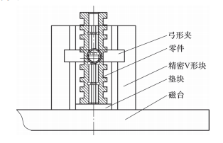
The positioning and tightening of the parts are illustrated in Figure 2. The positioning device consists of a magnetic table, a cushion block, a V -shaped precision block and arc pliers. The V -shaped block and stamp are the positioning reference, and the arc pliers is the tightening mechanism. This luminaire uses the outer circle and the end of the part as a reference to position the part. The positioning benchmark coincides with the process mark and the positioning precision is high. At the same time, the pliers has a simple structure and is easy to use.
Figure 2 Positioning and tightening of the part
(3) Design of tool electrodes The principle of EDM is based on the phenomenon of electrical corrosion during a pulsed spark discharge between the tool and the part (positive and negative electrodes) to eliminate excess excess metal to obtain the predetermined size, shape and quality of the room. . processing requirements[2]. The electrode of the circular tool is used to continuously unload the annular groove in order to complete the treatment of the indoor indoor precision groove. The form and precision of the electrode directly affect the precision of the machining. The tool electrode is illustrated in Figure 3. The shape is a cylinder with a bell mouth. The cylindrical surface is used to align the center of the room. The 0.2 mm plan on the right end surface guarantee that the electrode is aligned. Contact during electroerosion machining, so that the groove of the inner ring thus treated works. The edge jumps to pass.

Figure 3 Tool electrode
Determination of the electrode size: dimension of electrode thickness B = (annular groove width 2.2 mm – 0.2 mm machining) – 0.05 mm. Diameter of the electrode D = (diameter of the inner hole 7.8 mm – deviation 0.2 mm) – 0.05 mm. At the same time, it is also necessary to take into account the diameter of the electrode D> Diameter of the annular groove 9.6 mm – diameter of the inner hole 7.8 mm + diameter of the 5 mm electrode rod. To ensure that the electrode has enough cutting edges.
(4) Planning of the machining trajectory: during treatment, the movement trajectory of the tool electrode must be planned first, so that the cutting surface of the electrode moves along the edge of Work on the groove of the inner precision ring to obtain the best position and posture of the electrode.[3]. It is only by planning the optimal trajectory of the movement of the electrode that can be guaranteed the quality and efficiency of the precise treatment of the grooves of the inner ring. As shown in Figure 1, the precision interior ring groove is symmetrical, the work edges 1# and 3# of the ring groove are in the same direction, and the 2# and 4# are in the same direction. During treatment, one end is treated first, then the other end is returned. When processing an inner ring groove of unique precision, it is necessary to carry out an automatic positioning of the electrode, a rapid movement during the treatment in the slow motion and a precise operation during the interpolation treatment. The automatic positioning trajectory is illustrated in Figure 4, and the rapid movement of the tool electrode and the interpolation processing is illustrated in Figure 5. When the automatic positioning of the electrode, the speed of Rotation must be maintained at 100 rpm, so as to guarantee the accuracy of the automatic positioning of the electrode.

Figure 4 Automatic positioning trajectory
The unique movement trajectory of the tool electrode for the machining of interior precision grooves is as follows: the tool electrode moves quickly to the treatment position of the annular groove, then the Linear interpolation deals with the radius of the annular groove, then the interpolation in arc treats the annular groove. The treatment is finished, it comes back from Plan XY and moves again. Repeat the treatment of linear interpolation and arc interpolation to the depth specified until the requirements of the process are met. Based on the analysis of the machining course of a single annular groove, to complete the treatment of several annular grooves, it is necessary to repeat the positioning and interpolation trajectories illustrated with figures 4 and 5 to finish treatment of all the interior grooves of precision of the ring. whole part. Note that when processing ring grooves 2# and 4#, you must return, tighten and align the parts before you can repeat the operation to treat the precision grooves of the inner ring.
(5) The electrical machining parameters determine that the axial position margin of an inner ring groove of unique precision is 0.12 mm, which must be divided into draft and finish machining. The total tolerance for the draft is 0.06 mm, the total tolerance for the semi-finition is 0.05 mm and the total tolerance for the finish is 0.01 mm. The distribution of the cutting depth for the draft and the finish is 0.02 to 0.03 mm/time for the draft, 0.01 mm/time for semi-finition and 0.005 mm/time for The finish. After debugging and verification, the cutting parameters are presented in Table 1.
Table 1 cutting parameters

In Table 1, a positive polarity is selected during coarse machining and semi-finished machining, and a narrow pulse width and a relatively large current are used to treat the annular groove. The loss of electrode is low and the processing speed is rapid.[4]. Select the negative polarity during the finish and use wide pulses and a weak current to treat the annular groove. The loss of electrode is low and the machining accuracy is high.[2]But due to the slow treatment speed, the finishing margin cannot be too large, otherwise the treatment time will be very long.
(6) Detection method The key parameters which must be detected for the inner ring grooves of precision are the size of the slit, the roughness of the surface, the axial circular beat of the work edge and the size of the point. The roughness of the surface is the guaranteed electrical machining parameter, while the size of the slit and the work. On the edge, the axial circular rundy of the edge and the cutting edge of the edge edge should be detected using special test equipment. Due to the high precision of the parts and the presence of the detection part inside the parts, after comparative analysis, a universal tool microscope was selected for the inspection. The X and Y coordinate races of the equipment are 200 mm and 100 mm, and the resolution is 0.0002 mm. , which can meet the measurement requirements. Detection clamping is represented in Figure 6.

Figure 6 Detection and tightening
Use the 30x eyepiece on the universal tool microscope to align the V-shaped precision block and tighten it. During the inspection, place the part on the V -shaped block. Place the small bulb of the right end in the groove of the inspection ring. Eye of the microscope to detect oil leaks. Dimensions linked to the groove of the holes detection ring. The inspection sequence of the inner ring groove is as follows: ① Detect the 0.004 mm axial circular random on the work side of the ring of the ring and the size of the bright ridge on the side of work . ② Check the position, size and width of the ring groove.
(7) Test results and analysis on the basis of the above analysis, a test treatment was carried out (see Figure 7) and 100 pieces have been tested and verified. After the measurement, the width of the ring groove was 2.2-0-0.1 mm and the size of the position. (20 ± 0.03) mm, (30 ± 0.03) mm and roar value of surface RA = 0.4 μm, the success rate is 100 %, the axial circular random of the annular groove is 0.004 mm and the cutting edge of the RMAX work edge = 0.01 mm, the success rate is 95%.

a) The groove of the ring is being treatment

b) Annular groove after treatment
Figure 7 Treatment of annular grooves
5 Concert
After analyzing the process of typical parts of inner ring groove of precision, this article determines the key factors affecting the treatment of ring grooves, analyzes the reasons and formulates targeted solutions. Thanks to a series of optimized conceptions of electroerosion equipment, tool electrodes, fixings, planning of machining trajectories and electrical machining parameters, the problem of machining the inner ring grooves high precision has been successfully resolved. Successful verification of mass production tests and conditions. It also provides reference ideas for the transformation of other similar products.
Daguang focuses on providing solutions such as precision CNC machining services (3-axis, 4-axis, 5-axis machining), CNC milling, 3D printing and rapid prototyping services.


