Burrs after machining are very annoying. The existence of burrs not only reduces the processing accuracy and surface quality of the workpiece, affects product performance, and sometimes even causes accidents. For the burr problem, people usually use the deburring process to solve it. Deburring is a non-productive process, which not only increases product costs and prolongs the production cycle of the product, but improper removal of burrs may also lead to the scrapping of the entire product, resulting in losses economic. In this article, the author first systematically analyzes the main factors affecting the formation of milling burrs, and discusses the methods and technologies to reduce and control milling burrs from structural design to manufacturing.
1. The main forms of burrs in end mill processing
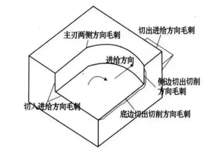
According to the cutting – tool burr classification system, the burrs generated in the end milling process mainly include burrs on both sides of the main edge, burrs on the cutting side in the cutting direction, burrs on the edge lower cutting in the direction of the cut. cutting direction and cutting and cutting feeds. There are five forms of directional burrs (see Figure 1).
Figure 1 Burr formed by end milling
Generally speaking, compared with other burrs, the burrs in the cutting direction of the lower edge are larger and more difficult to remove. For this reason, this paper considers the cutting burrs of the lower edge in the cutting direction as the main research object. According to the size and shape of the burrs in the cutting direction of the bottom edge during end milling, they can be divided into the following three types: Type I milling cutters (larger, difficult to remove and more expensive to remove), Type II burs (larger, difficult to remove and expensive to remove) small, cannot be removed or can be easily removed) and Type III burs are negative burs (see Figure 2).

Figure 2 Types of burrs in the cutting direction when cutting the bottom edge during milling
2. Main factors affecting the formation of end burrs
Burr formation is a very complex material deformation process. Various factors such as workpiece material properties, geometry, surface treatment, tool geometry, tool cutting path, tool wear, cutting parameters and The use of coolant directly affects the formation of burrs. Figure 3 is a block diagram of the factors affecting end mills. Under specific milling conditions, the shape and size of end mills depend on the overall effect of various influencing factors, but different factors have different effects on burr formation.

Figure 3 Control chart of causes and effects of milling burr formation
1.Tool entry/exit
In general, the burrs generated when the tool rotates out of the workpiece are larger than the burrs generated when the tool rotates into the workpiece.
2. Cut out the corners of the plane
The cutting angle of the plane has a great influence on the formation of burrs in the cutting direction of the lower edge. The definition of plane cutting angle is that when the cutting edge rotates away from the end surface of the workpiece, in the plane passing through a point on the cutting edge perpendicular to the axis of the cutter, the direction of cutting speed (the vector combination of tool speed and feed rate) at this point is the same as the angle between the direction of the end faces of the workpiece. The direction of the end surface of the workpiece is from the tool screwing point to the tool unscrewing point.
The test results show that the height of the burr changes as the cutting depth changes, that is, as the cutting depth increases, the burr changes from Type I burr to a type II burr. The minimum milling depth that produces Type II burrs is generally referred to as the limiting cutting depth, expressed as dcr. Figure 4 shows the effect of in-plane cutting angle and cutting depth on burr height when machining aluminum alloy.

Figure 4 Burr shape, plane cutting angle and cutting depth
It can be seen in Figure 4 that the greater the plane cutting angle, the greater the limiting cutting depth; when the plane cutting angle is greater than 120°, the size of type I burrs is larger, and the cutting depth limit which changes to type II burrs are also large. Therefore, a small plane cutting angle is conducive to the generation of type II burrs. Indeed, the smaller φ, the more the supporting rigidity of the end surface is relatively improved and burrs are less likely to form.
The size and direction of the feed rate will have some impact on the size and direction of the resulting speed v, which will then impact the plane rake angle and burr formation. Therefore, the larger the feed rate and the exit edge offset angle α, and the smaller φ, the better it is possible to suppress the formation of larger burrs (see Figure 5).

Figure 5 Effect of feed direction on burr formation
3. EOS tooltip output sequence
When end milling, the size of the burrs depends largely on the sequence of exit of the tool tip. As shown in Figure 6: point A is the point on the minor cutting edge, point C is the point on the major cutting edge, and point B is the top of the tool tip. The tool tip is assumed to be sharp, i.e. the arc radius of the tool tip is not taken into account. If edge BC exits the workpiece first and edge AB exits the workpiece later, the chips hinge on the machined surface. As milling continues, the chips are pushed out of the workpiece, forming a larger burr on the lower edge in the direction of the cut. If edge AB exits the workpiece first and edge BC exits the workpiece later, the chips are hinged on the transition surface and are cut away from the workpiece, forming a smaller cutting burr on the lower edge in the cutting direction.

Figure 6 Sequence of tool tip exit and burr formation
Tests show:
①The tool tip output sequence ABC/BAC/ACB/BCA/CAB/CBA which increases the size of the burr in sequence.
②The results produced by EOS are the same, except that under the same output sequence, the size of burrs produced by plastic materials is larger than that of fragile materials. The tool tip exit sequence is not only related to tool geometry, but also to factors such as feed, milling depth, workpiece geometry, and milling conditions. cut. It is a combination of several factors that influence the formation of burrs.
4. Influence of other factors
① Milling parameters, milling temperature, cutting environment, etc. will also have some impact on the formation of burrs. The influence of some major factors such as feed rate, milling depth, etc. is reflected in the plane rake angle theory and the. tooltip output sequence EOS Theory No need to go into details.
②The better the plasticity of the workpiece material, the easier it is to form type I burrs. In the end milling process of fragile materials, if the feed quantity or plane cutting angle is large, this promotes the formation of type III burrs (defects).
③When the angle between the end surface of the workpiece and the machined plane is greater than a right angle, the formation of burrs can be suppressed due to the improved support rigidity of the end surface.
④Using milling fluid is beneficial to extend tool life, reduce tool wear, lubricate the milling process and thus reduce burr size.
⑤ Tool wear has a great impact on burr formation. When the tool wears to a certain extent, the arc of the tool tip not only increases in the tool exit direction, but also the shaped burrs. generated in the cutting direction of the tool. The mechanism needs to be studied further.
⑥Other factors such as tool materials also have a certain impact on the formation of burrs. Under the same cutting conditions, diamond tools are more conducive to removing burr formation than other tools.
3. Basic methods for controlling the formation of milling burrs
End burr formation is affected by many factors. It is not only related to the specific milling process, but also to the workpiece structure, tool geometry and other factors. To reduce milling burrs, the generation of burrs must be controlled and reduced in many aspects.
1. Reasonable structural design
The formation of burrs is largely influenced by the structure of the part. With different part structures, the shape and size of the burrs on the edges after processing are also very different. If the part material and surface treatment are predetermined, the geometry and edges of the part are an important factor in determining burr formation.
2. Proper treatment sequence
As shown in Figure 7, the processing sequence also has a certain impact on the shape and size of end mills. The shape and size of the burrs are different, as well as the associated deburring workload and costs. Therefore, choosing the appropriate processing sequence is an effective way to reduce the cost of deburring.

(a) (b)
Figure 7 Select Processing Sequence Control Method
In Fig. 8a, if the plane is drilled first and then the plane is milled, large milling burrs will be easily generated on the circumference of the hole; if the plane is first milled and then the hole is drilled, there will only be smaller ones; drill burrs around the circumference of the hole. Similarly, in Fig. 8b, the size of the burr formed by first milling the top surface and then milling the concave profile is smaller than that of the burr formed by first milling the concave profile and then milling the surface flat.

(a) (b)
Figure 8 Tool path control method
3. Avoid tool exit
Avoiding tool withdrawal is an effective way to avoid burr formation, because tool withdrawal is the main factor in burr formation in the cutting direction. Normally, the burrs produced when the cutter is rotated out of the workpiece are larger, and the burrs produced when the cutter is screwed into the workpiece are smaller. Therefore, strawberry should be avoided as much as possible during treatment.
4. Choose the appropriate cutting path
From the previous analysis, it can be seen that when the cutting angle of the plane is less than a certain value, the size of the generated burrs is smaller. The cutting angle of the plane can be changed by changing the milling width, the feed rate (amplitude and direction) and the rotation speed (amplitude and direction). Therefore, the generation of Type I burrs can be avoided by selecting an appropriate tool path.
5. Select the appropriate milling parameters
End milling parameters (such as feed per tooth, end milling width, end milling depth and tool geometric angle, etc.) have a certain impact on the formation of burrs .
The formation of milling burrs is affected by many factors, among which the main influencing factors are: tool exit/entry, plane cutting angle, tool tip exit sequence. tool, milling parameters, etc. The final shape and size of the cutter is the result of a combination of factors.
This article starts from the whole process of workpiece structural design, machining process layout, milling quantity and tool selection, analyzes the main influencing factors of milling burr and provides methods for controlling cutter routes, selecting appropriate processing sequences, and improving structural design. The technologies, processes and methods used to remove or reduce milling burrs provide feasible technical solutions to actively control burr size, improve product quality, reduce costs and shorten production cycles during milling processing.
Daguang focuses on providing solutions such as precision CNC machining services (3-axis, 4-axis, 5-axis machining), CNC milling, 3D printing and rapid prototyping services.


