The cylinder block is also called the engine block. It is the “skeleton” of the engine and the basis for assembling the various mechanisms and systems of the engine. All major engine parts and accessories are installed inside and outside of it to withstand various. loads. Therefore, the cylinder must have sufficient strength and rigidity. The main parts installed on the cylinder include cylinder head, crankshaft, oil pan, piston and connecting rod assembly, etc. The main accessories connected to the cylinder include water pump, oil pump, generator and starter, etc. At the same time, the cylinder block also serves as the main transport channel for coolant and engine oil.
The structure and characteristics of the cylinder
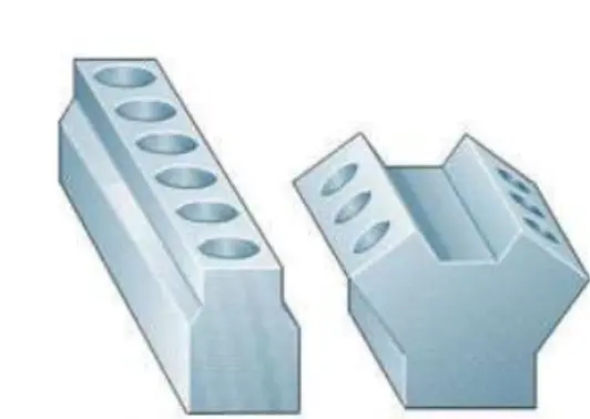
Structure: parts of complex shape, thin-walled, box-shaped
Features:
Have sufficient strength and rigidity
Has a good seal
Hexahedral appearance, thin-walled porous parts
Reliable cooling
Liquid flows easily
1
About cylinder classification
Classification of the outer structure of the cylinder
Commonly used engine block structures for passenger cars include in-line engines and V-shaped engines.
An in-line engine means that all the cylinders are arranged side by side in a plane. The V-shaped engine divides all cylinders into two groups and arranges adjacent cylinders together at a certain angle (usually 60°), so that the two cylinder groups form two planes with a certain angle when viewed from the side. are V-shaped, that’s why it is called V-shaped engine. Generally speaking, V-shaped engines have at least 6 or more cylinders and a displacement greater than 2.5L. They are often configured in mid-to-high-end passenger cars. The cylinders of the in-line engine are arranged in a row. The structure of the cylinder block, cylinder head and crankshaft is relatively simple, the manufacturing cost is low, and the fuel consumption is low, so it is widely used in domestic vehicles. .
Structure of main bearing hole to be classified
According to the different structure of the main bearing hole of the cylinder block, the cylinder block is generally divided into the following two forms:
① Gantry cylinder (deep skirt):
The characteristic is that the main bearing hole is composed of a cylinder block and a split tile cover. The advantages of this type of cylinder are good strength and rigidity, relatively simple structure and relatively low manufacturing cost. The structure is shown in the figure.

② Tunnel cylinder (base plate):
The main bearing hole of this type of cylinder is composed of the cylinder block and the integrated tile cover (lower cylinder block). Its advantage is that it has good rigidity and strength, which improves the strength of the tile covering, so it is generally more suitable for some high-power engines. But the manufacturing cost is higher. The structure is shown in the figure.

Cylinder material to be classified
The engine block is generally cast by gray cast iron, which has sufficient toughness, good wear resistance, good heat resistance, good shock absorption, good casting performance and machinability, and is good walk. However, in recent years, in order to meet the requirements of reducing the overall quality of the vehicle, a large number of alloy materials have been used in the engine block. The most widely used alloy material is aluminum alloy. It is worth noting that in the aluminum alloy cylinder block, the cylinder material is not aluminum alloy, but still cast iron. This is mainly due to cost considerations. Although the weight of the all-aluminum alloy cylinder is even lighter, due to the high friction coefficient of the cylinder wall, if an aluminum alloy cylinder bore is used, expensive materials and processes such as Silicon-aluminum alloy and metal ion spraying of an inner cylinder wall will be required, which will significantly increase the cost of the engine block. Therefore, in aluminum alloy cylinder blocks, the cylinder bore is generally inlaid with a cast iron cylinder liner, which ensures the wear resistance of the cylinder bore and also reduces the weight of the cylinder block.


Gray cast iron (photo on the left) | Aluminum alloy (pictured right)
2
Introduction to the main parts of the cylinder

Top of cylinder – flat surface
The upper plane of the cylinder is also called the surface of the combustion chamber, as shown in the figure. This surface is used to install the engine cylinder head and together with the cylinder head forms the combustion chamber. A mixture of high temperature and high pressure gases burns inside. Therefore, the quality requirements for the upper plane of the cylinder are very high.
For example: Generally, the flatness precision of the upper plane of the cylinder is 0.05 mm. In addition to Rz requirements, surface roughness also has weight requirements.

Cylinder block-cylinder bore:
Taking an in-line 4-cylinder engine as an example, the cylinder block has 4 cylinder holes. When the engine is running, the piston moves back and forth up and down in the cylinder bore. Therefore, the cylinder bore opening size, surface roughness, verticality, roundness, cylindricity and other characteristics are very important and will directly affect engine performance. engine. . Here are the relevant parameters and indicators of the LGE cylinder block regarding the cylinder bore:

 Cylinder block cylinder bore
Cylinder block-crankshaft bore:
Just like the cylinder bore, the crankshaft bore is also the most important bore system of the cylinder block. In the engine assembly line, the main bearing (equivalent to a plain bearing) must first be installed in the crankshaft hole, and then the shaft must be installed. Among them, the main journal of the crankshaft rests on the bearing. In order to ensure that the crankshaft can rotate normally in the bearing, there will be a certain space between the main journal of the crankshaft and the bearing, but this gap cannot be too large, otherwise it will increase the noise of the engine. and cause excessive engine vibration. Therefore, some products will require the pads to be grouped and matched. That is, before installing the bearings, the diameter of the crankshaft hole in the cylinder block and the diameter of the main journal of the crankshaft must first be measured, as well as a bearing. a bushing of appropriate thickness should be selected based on the actual values of these two diameters. The crankshaft hole is composed of upper and lower semi-circular holes: the upper semi-circular hole is in the upper cylinder block, and the structure of the lower semi-circular hole is different in design. Some products are located in the lower cylinder block. , and some are in the upper bearing cap. But whether it is the lower cylinder block or the axle cover, they are attached to the upper cylinder block by bolts, so that the upper and lower semicircular holes form a complete crankshaft hole.
The main characteristics of the crankshaft bore are the diameter, coaxiality between the crankshaft bores and the surface roughness of the crankshaft bore. Among them, the crankshaft hole diameter tolerance is generally controlled within 0.01mm, the coaxiality tolerance is generally controlled within 0.05mm, and the surface roughness Ra tolerance should be less than 1, 6um.

Cylinder body – front side
The front end surface of the cylinder block is usually installed with important engine accessories such as water pump and oil pump assembly (including crankshaft front oil seal), so that the flatness, verticality and roughness of this surface are very important.
Example: The surface flatness tolerance of the front end of the LKG cylinder is less than 0.1, the verticality tolerance is less than 0.15, and the surface roughness has weight requirements in addition to the weight requirements. Rz.

Cylinder block-rear side
The rear side of the cylinder is usually installed with a flywheel or transmission. Therefore, like the front face of the cylinder, this face will control parameters such as surface flatness, verticality and roughness, and the precision is basically in accordance with the requirements. from the front panel.

3
How to organize the cylinder process and select the positioning mark

First, remove the excess processing layer from the large area to ensure that the deformation after finishing is small.
Processes in which internal defects are easily detected should be organized first.
Arrange the processing of deep holes in the previous process as much as possible to avoid large internal forces affecting subsequent finishing processes or causing tool breakage.
Process planning
First the base, then other things: for example, deal with one side and two pins first
Surface first, then hole: process the flat surface first and cut off the hard layer on the surface, which can avoid drilling deviations and cuts caused by surface protrusions, burrs and hard spots, and improve the accuracy of hole processing.
Separation of rough and fine machining: It is helpful to eliminate thermal deformation and internal stress generated during rough machining and improve the precision of finish machining. It promotes rapid detection of waste and avoids wasted labor hours and production costs.
Process concentration: in order to reduce processes, reduce machining equipment and reduce costs. Processing should be concentrated as much as possible to improve production efficiency and processing precision. Concentrating related hole processing on a single machine tool can also reduce positioning errors caused by repeated positioning, particularly improving position accuracy.
Cylinder processing positioning reference
There are three common positioning datums in cylinder processing: rough datums, rough datums, and fine datums. During machining, the raw data is generally positioned in the first process of the production line to process the raw data. In subsequent processes, the raw data is positioned to process the fine data.
1. Blank benchmark:
The function of the raw reference is to use its positioning to process the raw reference of the cylinder body. Different cylinder products may have different blank part numbers. Generally, blank references should limit the degrees of freedom in the three linear directions and three rotational directions of the cylinder, as shown in the figure below.
Cylinder processing positioning reference


2. Coarse reference:
The function of the rough reference is to complete the rough machining of the cylinder block, especially the machining with large margins and heavy cutting loads, such as the rough machining of the lower plane, upper plane, front end face, rear end face, cylinder bore, crankshaft bore, etc. of the cylinder block. In addition, another function of the coarse reference is to position, so as to process the fine reference of the cylinder body. Typically, rough datums are primarily used for positioning end faces.
rough data


3. Good benchmark:
Common precision reference shapes of the cylinder generally include lateral positioning, oil pan surface positioning, lower cylinder seal surface positioning, and crankshaft hole positioning. The first three types all belong to the “two pins on one side” shape. In the “two pins on one side” positioning method, the two positioning pins on the fixture are preferably a round pin and the other is a diamond pin. The goal is to avoid excessive positioning. The center line connecting the two arc segments in the diamond pin must be perpendicular to the circular pin, as shown in the figure below, otherwise overpositioning will occur, preventing the two fixture positioning pins from entering the two positioning pins; holes in the rigid body normally.


If the two positioning pins are round pins, in order to avoid excessive positioning, the corresponding gap between the positioning pins and the pin holes should be increased, otherwise the positioning pins will not be able to enter the holes of the process pins. Therefore, using the “two pins on one side” solution using two round pins, the positioning accuracy is slightly lower because the corresponding gap between the round pins and the process pin holes is larger than the solution of ‘a round brooch and a diamond brooch.
Features processed using crankshaft hole positioning are typically critical and closely related to the functional operation of the product, such as combustion chamber surfaces, front and rear end surfaces, and cylinder bores.

4
Cylinder Block Process Sequence Table


5
Cylindrical tool display (part)


Surface milling of tile cover joint


Crankshaft Coarse Bore


Coarse Bore Cylinder Bore
Daguang focuses on providing solutions such as precision CNC machining services (3-axis, 4-axis, 5-axis machining), CNC milling, 3D printing and rapid prototyping services.


