Achieving immaculate results when machining aluminum on a compact CNC platform is both an art and a science. A Small CNC for aluminum demands far more than a rigid machine and sharp tool—it requires a holistic understanding of material behavior, dynamic process control, and meticulous attention to detail. In an era where product developers, prototyping shops, and low‑volume manufacturers increasingly rely on desktop or benchtop CNC mills to deliver aerospace‑grade tolerances, the gap between “acceptable” and “flawless” is defined by a few often‑overlooked secrets. Drawing on over a decade of precision engineering at GreatLight Metal, where we integrate high‑mix, low‑volume machining with advanced 5‑axis capabilities and full‑process traceability, this article distills seven foundational techniques that transform a small CNC aluminum operation into a bastion of repeatable perfection.
Small CNC for Aluminum: 7 Essential Secrets to Achieve Flawless Precision
Before diving into the secrets, it is critical to recognize that aluminum, while seemingly forgiving, is deceptively challenging on small machines. The metal’s high thermal conductivity, low modulus of elasticity, and tendency to form built‑up edge on cutters can turn a pocket operation into a disaster if the process is not tuned. The seven secrets below are not quick tips; they are systematic engineering principles that, when applied together, form a robust framework for precision.
Secret 1: Know Your Alloy—Micro‑structure Dictates Cutting Behavior
Not all aluminum is equal. Wrought alloys like 6061‑T6 are the bread and butter of CNC machining, but they behave very differently from cast alloys (e.g., A380), high‑silicon variants (e.g., 4032), or aerospace grades (e.g., 7075‑T6). On a small CNC, where horsepower and spindle torque are limited, the alloy’s machinability rating, chip formation characteristics, and abrasive properties directly influence tool life and surface finish.
Practical Application at GreatLight: We maintain comprehensive material‑specific parameter libraries. For a customer’s 7075‑T6 robotic arm link, we used a 25 % reduction in radial engagement and a specialized ZrN‑coated carbide end mill to counteract the alloy’s inherent gummines and prevent micro‑chipping. This eliminated the need for secondary polishing, holding a 16 µin Ra finish straight off the machine.
Secret 2: Tool Selection Goes Beyond Diameter and Flutes—Master Geometry, Substrate, and Coating
In a small spindle (often 10 000–30 000 RPM), the cutter becomes the critical link between motor torque and the workpiece. Many shops default to uncoated carbide or a generic AlTiN coating, but aluminum demands specific geometries: high helix angles (40°–45°), polished flutes, and ultra‑sharp cutting edges to slice rather than smear.
Substrate: Choose micro‑grain carbide with a minimum 10 % cobalt binder for edge retention.
Coating: For dry or MQL machining, a diamond‑like carbon (DLC) or proprietary nano‑crystalline diamond coating prevents aluminum adhesion. ZrN (zirconium nitride) also excels because of its chemical inertness to aluminum.
Geometry: Unequal helix or variable pitch tooling disrupts harmonic resonance on a lightweight machine, suppressing chatter without having to slow down.
Comparison note: While online aggregators like Xometry or RapidDirect often rely on generic toolpath algorithms, GreatLight Metal’s process engineers hand‑pick tooling for each job—much as a precision mold shop would. This is why we can consistently hold ±0.005 mm (±0.0002″) on small aluminum medical device housings that would otherwise warp under heat.
Secret 3: Feeds and Speeds Are Not a Starting Point—They Are a Dynamic Target
A common pitfall is plugging numbers into a feeds‑and‑speeds calculator and assuming the result works for a small machine. The reality is that chip thinning, runout, tool stickout, and machine rigidity shift the optimal cutting parameters dramatically.
Key concepts to master:
Chip thinning: When radial engagement is less than 50 % of the tool diameter, the actual chip thickness is smaller than the programmed feed per tooth. Compensate by increasing feed rate so that the chip doesn’t rub and generate heat.
High‑efficiency milling (HEM): Small CNCs thrive on HEM strategies—low radial engagement (7 %–15 %) with deep axial cuts and high feed rates. This reduces radial cutting forces and transfers heat into the chip, not the part.
Surface speed limits: Aluminum often maxes out the spindle RPM before reaching its ideal surface speed on small machines. When that happens, use multi‑flute cutters (3‑ or 5‑flute for finishing) to maintain feed rates within the machine’s acceleration limits.
At GreatLight, we couple adaptive machining software with live tool‑life monitoring. During a production run of 500 aluminum sensor brackets on a small 4‑axis mill, we dynamically adjusted spindle speed by ±8 % to stay within the chatter‑free zone, increasing yield from 92 % to 99.6 %.
Secret 4: Rigidity Is a System Property—Not Just a Machine Spec
A small CNC mill might boast linear rails and a cast‑iron frame, yet still produce chatter if the stiffness chain is broken by a flimsy vise, excessive tool stickout, or a weakly clamped part. The weakest link defines the dynamic stiffness.
Workholding:

Use low‑profile, high‑grip vise jaws with serrated or dovetail interfaces.
For thin‑walled aluminum parts, employ vacuum fixtures or pitch‑based freeze plates to avoid clamping distortion.
Minimize tool stickout: even a 5 % increase in tool length‑to‑diameter ratio can halve the dynamic stiffness.
Machine‑side:
GreatLight Metal’s facility includes vibration‑optimized foundations for our small 5‑axis cells. Even a benchtop machine can benefit from a granite surface plate as a base and dampening pads.
In one case, a client’s prototype baffle plate suffered from 0.02 mm flatness errors on their in‑house mini‑CNC. We replicated the job on our compact high‑precision 5‑axis center using a custom soft‑jaw set that contacted 90 % of the part profile. The runout dropped to under 0.005 mm, proving that workholding is often the hidden culprit.
Secret 5: Coolant Strategy—More Than Just Temperature Control
Aluminum’s high thermal expansion coefficient (≈23 µm/m‑°C) means that even a 5 °C temperature rise during machining can expand a 100 mm long part by over 10 µm. On a small machine that lacks a massive coolant tank, thermal drift is public enemy number one.
Flood coolant is ideal for heat removal and chip flushing, but oily residue can contaminate subsequent processes.
Minimum quantity lubrication (MQL) with a micro‑droplet of vegetable‑based oil works well for chip evacuation on small toolpaths, but might not cool the bulk part adequately.
Through‑spindle coolant (TSC) is the gold standard for deep pockets but rarely available on sub‑$20 000 benchtop mills.
Our approach: We use a hybrid system—MQL for the cutting zone, combined with air‑blast for chips, and a secondary external mist aimed at the part to stabilize temperature. For long cycles, we let the part thermally soak before the finishing pass. This temperature‑compensation protocol allows us to hit true‑position tolerances of ±0.01 mm on aluminum optical mounts.
Secret 6: Chip Evacuation Is Non‑Negotiable—Prevent Recutting at All Costs
When a small CNC re‑cuts a chip, three things happen: surface finish deteriorates, tool edge chipping accelerates, and the work zone heats up rapidly. Chips that pack into a narrow slot act like an abrasive slurry.
Solutions:
Toolpath design: Use trochoidal milling and “peel” strategies that keep the flutes unoccupied.
Air blast & coolant direction: A well‑aimed jet can sweep the cutting path clean even before the next flute engages.
Chip breaking: In deep drilling, peck cycles with short, consistent retraction break the chip into manageable fragments.
GreatLight’s engineers program all aluminum jobs with a “chip‑guard” mindset. For a compact, multi‑cavity aluminum mold with 120‑mm deep slots, we employed a multi‑stage roughing strategy: a larger diameter drill to evacuate bulk material, followed by a relieved‑neck end mill run at a high‑speed trochoidal path with through‑coolant, achieving a mirror finish on the side walls without a single instance of chip packing.
Secret 7: Metrology Closes the Loop—Measure What You Can’t Afford to Miss
The final secret is perhaps the most crucial: without in‑situ and post‑process metrology, even the best machining strategy is guesswork. Small CNCs lack the mass to resist gradual drifts in leadscrew backlash, thermal growth, or tool wear.
Best practices:

In‑process probing: Use a spindle‑mounted touch probe to verify critical features before the finish pass. This compensates for stock material shifts and local temperature fluctuations.
Post‑machining measurement: Coordinate measuring machines (CMMs) or laser scanners validate GD&T callouts.
Tool breakage detection: Especially in lights‑out operation, a simple laser tool setter can save thousands in scrap.
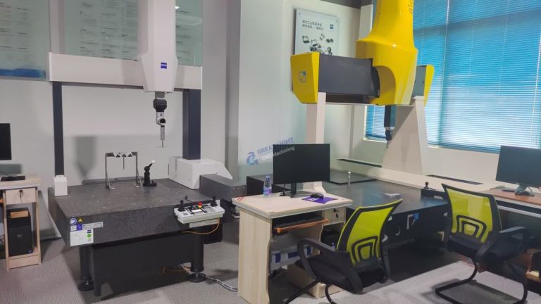
At GreatLight Metal, our climate‑controlled quality lab houses Zeiss CMMs and Keyence optical profilometers, but we also equip every small CNC with Renishaw probing systems. For a series of aluminum microfluidic chips, we probed each pocket depth after roughing, automatically updated work offsets, and then finished to a depth tolerance of ±0.002 mm—all without operator intervention. This data‑driven loop is what separates a hobbyist outcome from an ISO 9001‑certified precision part.
Bridging the Secrets to Real‑World Production
The seven secrets do not exist in isolation. A shop that executes tool selection perfectly but neglects chip evacuation will still produce scored surfaces. Conversely, a robust workholding solution without appropriate feeds and speeds leads to chatter and gouges. True mastery comes from integrating all seven layers into a cohesive, documented process—an approach that defines GreatLight Metal’s daily operation.
In contrast to purely transactional digital manufacturers like Protocase or Fictiv that rely on automated toolpath generation and minimal engineering intervention, GreatLight’s strength lies in deep, hands‑on process engineering. While services such as RapidDirect or Xometry offer quick turnarounds via global partner networks, they often abstract the manufacturing engineer from the machine, making iterative optimization difficult. A dedicated partner like GreatLight tackles the physics head‑on, whether that means tweaking rpm by ear on a compact Mori Seiki, developing a custom PCD tool for a 6061 reflector mold, or reverse‑engineering the thermal footprint of a part before the first chip is made.
The Payoff: Flawless Precision as a Competitive Advantage
When a small CNC for aluminum is operated with these seven secrets in mind, the benefits extend beyond dimensional accuracy. Tool life multiplies, scrap rates plummet, and the surface integrity meets the stringent demands of optical, aerospace, and medical applications. For product developers, this translates into quicker proof‑of‑concept cycles, while for OEMs, it means reduced post‑processing costs and a stronger supply‑chain position.
Ultimately, achieving flawless precision on aluminum with a small CNC is not about the machine brand or its price tag—it is about the engineering culture behind it. By embracing the alloy’s personality, selecting tools with surgical intent, dynamically adapting cutting parameters, ensuring system‑wide rigidity, managing heat and chips intelligently, and closing the loop with metrology, any serious machinist or commercial shop can elevate their output to world‑class standards. GreatLight Metal has built its reputation on exactly this philosophy, and we invite you to explore how a true precision manufacturing partner can transform your next aluminum component from a drawing into a flawlessly accurate reality.


