Gears are mechanical parts whose teeth can fit together. The gear transmission can perform functions such as deceleration, speed increase and direction change. It is widely used in mechanical transmission and the entire mechanical field. Today I will summarize the processing technology of gear parts.
01
The function and structure of gears
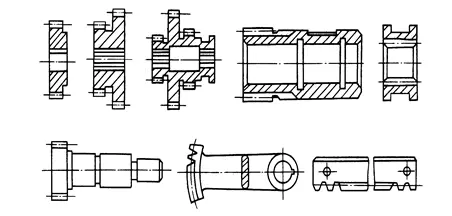
Although gears are designed in different shapes and sizes due to their different functions in the machine, they can still be divided into two parts: the ring gear and the wheel body. Common spur gears include the following categories (image below): disc gears, sleeve gears, internal gears, shaft gears, sector gears, and rack gears. Among them, disc gears are the most widely used.
Structural form of spur gear
A spur gear may have one or more ring gears. Ordinary single ring gears have good craftsmanship, while the small ring gears of double or triple gears are often affected by shoulders, which limits the use of some processing methods, and generally only the shaping of the gears can be used. If the precision of the gear is high and gear shaving or grinding is required, the multi-ring gear is usually made into a combined structure of a single ring gear.
02
Precision requirements for spur gears
The manufacturing precision of the gear itself has a great impact on the working performance, load capacity and service life of the whole machine. According to the conditions of use of gears, the following requirements are proposed for gear transmission:
1. Movement precision
The gear should transmit the movement accurately, and the transmission ratio is constant, that is, the rotation angle error of the gear should not exceed a certain range during one revolution.
2. Work stability
The movement of the gear transmission should be smooth and the impact, vibration and noise should be low. This requires limiting the variation of the instantaneous speed ratio as the gear rotates, i.e. limiting the rotation angle error over a short period.
3. Contact accuracy
When the gear transmits power, in order to avoid excessive contact stress due to uneven load distribution, causing premature wear of the tooth surface, it requires that the contact of the tooth surface be uniform when the gear operates and ensures a certain contact area. and a contact that meets the requirements.
4. Tooth side clearance
When gear transmission is required, a certain space is left between the non-functional tooth surfaces to store lubricating oil and compensate for dimensional changes caused by temperature and elastic deformation as well as some errors during processing and l ‘assembly.
03
gear material
Gears must be made of appropriate materials depending on the working conditions used. The choice of gear material has a direct impact on the processing performance and service life of the gear.
Generally, medium carbon steel (such as 45 steel) and low and medium carbon alloy steel are used for gears, such as 20Cr, 40Cr, 20CrMnTi, etc. Important gears with higher requirements can be made of 38CrMoAlA nitrided steel, and gears without power transmission can also be made of cast iron, bakelite or nylon and other materials.
04
Gear heat treatment
In gear processing, two heat treatment processes are organized according to different objectives:
1. Blank heat treatment
Organize a preheating normalization or tempering treatment before and after the treatment of the tooth blank. The main objective is to eliminate residual stresses caused by forging and rough machining, improve the machinability of the material and improve the overall mechanical properties.
2. Heat treatment of tooth surface
After tooth processing, in order to improve the hardness and wear resistance of the tooth surface, heat treatment processes such as carburizing quenching, high frequency induction heating quenching, carbonitriding and nitriding are often carried out.
05
Blank gear
The main forms of gear blanks include bars, forgings and castings. Bar stock is used for gears with small size, simple structure and low strength requirements. When gears require high strength, wear resistance and impact resistance, forgings are often used. For gears with a diameter greater than 400 to 600 mm, casting blanks are often used.
In order to reduce the amount of mechanical processing, for large size and low precision gears, the gear teeth can be cast directly; For gears with small size and complex shape, new technologies such as investment casting, die casting, precision forging, powder metallurgy, hot rolling and cold extrusion can be used. The process produces tooth blanks with gear teeth to improve labor productivity and save raw materials.
06
Selection of machining solutions for tooth blanks
For the tooth blanks of shaft gears and sleeve gears, the processing process is basically similar to that of general shafts and sleeves. Now we mainly discuss the processing process of disc gear tooth blanks. The machining process plan of tooth blank mainly depends on the structure of the wheel body and the production type of the gear.
1. Processing of mass-produced gear blanks
When processing medium-sized tooth blanks in large quantities, the process plan of “drilling, pulling and turning multiple tools” is often used.
(1) Drill or enlarge holes according to the outer circle and the positioning of the end face of the blank.
(2) Pull the holes.
(3) Use hole positioning to rough and finish the outer circle, end face, grooves and chamfering on a multi-tool semi-automatic lathe.
This process solution uses high-efficiency machine tools to form an assembly line or automatic line, so the production efficiency is high.
2. Gear blank processing for mass production
When producing tooth blanks in batches, the “one car, one car, one car” process plan is often used.
(1) Position the outer circle of the tooth blank or wheel hub and finish turning the outer circle, end face and inner hole.
(2) Use the end face to support the drawing hole (or spline hole).
(3) Position the outer circle and the end face of the machine with holes.
This solution can be achieved with a horizontal lathe or a turret lathe and a broaching machine. It is characterized by stable processing quality and high production efficiency.
When the tooth blank hole has steps or the end face has grooves, you can make full use of the multi-function tools on the turret lathe for multi-station processing and complete the tooth blank processing. tooth on the turret lathe in one go.
07
Gear tooth processing method
The processing of the tooth profile of the ring gear is the core of the entire gear processing. There are many processes in gear processing, all of which serve the purpose of tooth profile processing, the aim being to finally obtain gears that meet precision requirements.
According to the processing principle, tooth shape can be divided into forming method and generation method. Forming method is a method of cutting the tooth surface with a forming tool that fits the shape of the tooth slot of the gear to be cut, such as tooth milling, tooth broaching and grinding forming teeth.
The generation method is a method in which the gear cutter and the workpiece perform generation movement to cut the tooth surface according to the meshing relationship of the gear pair, such as gear hobbing. gears, gear shaping, gear shaving, gear grinding and gear honing. .
The choice of tooth profile processing scheme mainly depends on the precision level, structural shape, production type and production conditions of the gear. For gears with different precision levels, the commonly used tooth profile processing schemes are as follows:
(1) Gears with accuracy below level 8
Requirements can be met by cutting or shaping the quenched and tempered gears. For hardened gears, the processing plan can be: rolling (insertion) of teeth – processing of tooth ends – quenching – correction holes. However, the precision of tooth profile machining before quenching needs to be improved by one level.
(2) Level 6-7 Precision Gears
For hardened gears, you can use: coarse honing – fine hobbing – tooth end machining – fine shaving – surface hardening – calibration reference – lapping.
(3) Gears with level 5 accuracy or higher
Generally used: coarse gear hobbing – fine gear hobbing – tooth end processing – quenching – correction reference – coarse tooth grinding – fine tooth grinding. Gear grinding is currently the processing method with the highest precision and smallest surface roughness value in tooth shape processing. The highest precision can reach level 3~4.
1. Milling equipment
Gear precision level: below level 9
Tooth surface roughness Ra: 6.3 ~ 3.2 μm
Scope of application: in the production of one-piece repairs, processing of low precision external cylindrical gears, racks, bevel gears and worm gears.
2. Tooth extraction
Gear precision level: level 7
Tooth surface roughness Ra: 1.6 ~ 0.4 μm
Scope of application: mass production of 7-level internal gears. The manufacture of external gear spindles is complicated, so it is rarely used.
3. Gear cutting
Gear precision level: 8 ~ 7
Tooth surface roughness Ra: 3.2 ~ 1.6 μm
Scope of application: processing of medium-grade external cylindrical gears and worm gears in various mass productions.
4. Gear Shaping
Gear precision level: 8 ~ 7
Tooth surface roughness Ra: 1.6 μm
Scope of application: in various mass production, processing of medium-grade internal and external cylindrical gears, multi-link gears and small racks
5. Rolling (or inserting) teeth – quenching – sharpening
Gear precision level: 8 ~ 7
Tooth surface roughness Ra: 0.8 ~ 0.4 μm
Scope of application: gears for tooth surface quenching.
6. Gear hobbing – gear shaving
Gear precision level: 7 ~ 6
Tooth surface roughness Ra: 0.8 ~ 0.4 μm
Scope of application: mainly used for mass production
7. Gear hobbing – gear shaving – quenching – gear sharpening
Gear precision level: 7 ~ 6
Tooth surface roughness Ra: 0.4 ~ 0.2 μm
Scope of application: mainly used for mass production
8. Rolling (insertion) of teeth – quenching – grinding of gears
Gear precision level: 6 ~ 3
Tooth surface roughness Ra: 0.4 ~ 0.2 μm
Scope of application: used for gear tooth surface processing of high precision, low productivity and high cost
9. Gear bearing (insertion) – gear grinding
Gear precision level: 6 ~ 3
Tooth surface roughness Ra: 0.4 ~ 0.2 μm
Scope of application: used for gear tooth surface processing of high precision, low productivity and high cost
08
Treatment of tooth ends
The processing of gear tooth ends includes rounding, chamfering, chamfering and deburring, as shown in the figure below. Rounded and chamfered gears can easily enter the meshing state when changing gears, reducing the impact phenomenon. Chamfering eliminates sharp edges and burrs from tooth tips.

a) rounding b) chamfering c) chamfering
Treatment of tooth ends
The figure below is a schematic diagram of using a finger cutter to round the tooth end. During rounding, the cutter rotates at high speed and oscillates along an arc. After processing one tooth, the workpiece withdraws from the cutter, is indexed, and then quickly approaches the cutter to process the end of the next tooth. Tooth end processing should be carried out before gear quenching. It is usually performed after gear rolling (inserting) and before gear shaving.

Rounding of tooth ends
09
Spur gear spur gear processing process

High precision gears
1. Blank forging
2. Normalizing heat treatment
3. Rough turning shape, leaving 2mm machining allowance everywhere
Positioning data: outer circle and end face
4. Finish turning everywhere, the inner hole is at Φ84.8H7, leaving a grinding allowance of 0.2mm on the total length, and the rest at size
Positioning data: outer circle and end face
5. Control
6. Milling the tooth surface, leaving a grinding margin of 0.25-0.3mm.
Positioning reference: inner hole and end face A
7. Chamfer
Positioning reference: inner hole and end face A
8. Deburring by fitter
9. High frequency quenching of tooth surface HRC52
10. Key slot
Positioning reference: inner hole and end face A
11. Grind the large end face A
Positioning reference: inner hole
12. Grind surface B along the entire length
Positioning reference: end face A
13. Grind the inner hole to φ85H5
Positioning reference: inner hole and end face A
14. Grinding the tooth surface
Positioning reference: inner hole and end face A
15. Control
10
Gear machining process analysis
1. Selection of the positioning reference
The selection of gear positioning marks often differs depending on the structural shape of the gear. Gears with shafts mainly use center positioning and when the hole diameter is large, taper plugs are used. The accuracy of top positioning is high and the reference can be unified. The following two positioning and clamping methods are often used when processing the tooth surface of gears with holes.
(1) Use the positioning end face clamping method. This method can match positioning data, design data, assembly data and measurement data, with high positioning accuracy and suitable for mass production. However, the manufacturing precision of the luminaire must be relatively high.
(2) The corresponding gap between the workpiece and the fixture chuck when positioning the workpiece on the outer circle and the end face is large. Use a dial indicator to calibrate the outer circle to determine the center position and position it with the end. face; clamp on the other end face. This method has low production efficiency because each part must be calibrated; it requires high coaxiality of the inner and outer circles of the gear blank, but does not require high precision for assembly, so it is suitable for single parts and small batches. production.
2. Gear blank processing
The processing of gear blanks before tooth surface processing occupies a very important position in the entire gear processing process, because the reference used for processing and inspection of the tooth surface must be processed at this stage, whether it is to improve productivity or ensure gear processing quality; Gear, all need to pay attention to the processing of gear blanks.
Among the technical requirements for gears, attention should be paid to the dimensional accuracy requirements of the tooth adding circle, because the tooth thickness detection is based on the tooth adding circle. If the accuracy of the tooth adding circle is too low, the tooth thickness measured. The value will inevitably be incorrect. Reflects the size of the tooth side clearance.
Therefore, the following three points should be considered during this treatment process:
(1) When using the diameter of the tooth tip circle as the measurement reference, the dimensional accuracy of the tooth tip circle should be strictly controlled.
(2) Ensure mutual perpendicular between the positioning end face and the positioning hole or outer circle
(3) Improve the manufacturing accuracy of the gear inner hole and reduce the corresponding gap with the fixing chuck.
Daguang focuses on providing solutions such as precision CNC machining services (3-axis, 4-axis, 5-axis machining), CNC milling, 3D printing and rapid prototyping services.


