The sharp-edged burrs of parts with special ring groove structures are located in the ring groove and cannot be observed with the naked eye. It is very difficult to remove burrs, which affects the quality of parts. Summarize and classify commonly used deburring methods and check the deburring effect to solve the problem that special ring groove burrs cannot be removed cleanly, and provide reference for solving the problem of sharp-edged burrs on parts with special ring groove structures.
1 Preface
Since burrs generated during the processing and manufacturing of mechanical parts can have adverse effects on the precision, performance and even the entire parts assembly system, thereby affecting the overall product quality, these In recent years, various industries have paid more and more attention to burr removal. Many researchers and technicians have conducted in-depth research on deburring methods.[1-3]。
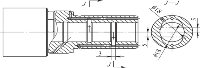
A certain type of special ring groove structural part is shown in Figure 1. The material is surface hardened steel and has a special ring groove structure. The annular groove of the hole is also processed with an eccentric annular groove, which is equivalent to the special annular groove. structure of a groove within a groove. The hole diameter is about 20mm, the eccentric ring groove diameter is slightly smaller than the center hole diameter, the eccentric ring groove eccentricity is greater than 5mm, the groove width is less than 5 mm and there are several deep holes of about φ2mm connected to the groove of the eccentric ring. The design requires a rounded corner of R0.3mm at the junction. During processing, it was found that after the eccentric ring groove was connected to the φ2mm deep hole, there were many sharp-edged burrs at the intersection, and it was difficult to remove them. Therefore, it is necessary to explore the method of removing sharp items. edge burrs of this special annular groove to ensure product quality.
Figure 1 Special structural parts with ring groove
2 Classification of commonly used deburring methods
In order to better apply deburring methods, commonly used deburring methods are summarized and classified, as shown in Figure 2, to facilitate testing and research of different deburring methods.

Figure 2 Classification of commonly used deburring methods
2.1 Mechanical deburring
Mechanical deburring is one of the most widely used deburring methods. It has strong applicability and is suitable for deburring most simple parts. Mechanical deburring method mainly refers to the use of cutting tools, sandpaper and oil stones to remove burrs from parts of turning, drilling, milling and grinding equipment. There are also bench workers who use various files and wire brushes (wheels) to do this manually. polish and remove burrs. Manual grinding and deburring is only suitable for rough machining and deburring. For some parts with special structures, manual grinding and deburring are difficult and require non-standard customized tools. For mechanical deburring for finishing, there are generally methods such as grinding deburring, wheel polishing machine deburring, abrasive belt polishing machine deburring and polishing machine deburring the end faces.
2.2 Chemical deburring
Chemical deburring methods mainly include electrolytic deburring and plasma polishing deburring.
Electrolytic deburring uses the electrochemical principle of anodic oxidation and dissolution of metal parts in the electrolyte. The metal part is the anode and the electrode is the cathode. When a direct voltage is applied between the two poles, the electrolyte flows through the gap between the two poles under a certain pressure, and the current density generated by the burrs and edges of the workpiece is the most large, causing rapid dissolution of burrs or round. The advantage of electrolytic deburring is that electrolysis is not limited by the hardness and shape of the parts, is suitable for all conductive materials, does not produce secondary burrs, has no residual stress, is suitable for mass production and can be easily automated. Electroplated deburring is suitable for small and medium-sized workpieces or small and medium-sized burrs and small burrs, and can round small corners. But this also has disadvantages, namely that the equipment is expensive and the electrolysis device is highly specialized. When the burrs in the electrolysis part are very large, the large burrs should first be removed by other means. Chemical corrosion, environmental pollution and fire. should be avoided during treatment.
Plasma polishing deburring is an electromagnetic gas discharge phenomenon that uses the principles of electrochemistry and plasma reaction. Under the pressure of the electric charge, ionic ozone is generated between the polishing fluid and the metal part. When the ions of this gas reach a certain number, it forms a plasma under the influence of positive ions, the ions are replaced on the surface. metal to achieve the deburring effect. The advantages of plasma polishing deburring are complete, thorough and efficient deburring. But it also has disadvantages, that is, the hole burr removal effect is average, and the deep hole deburring effect is poor. When the time setting is too long, sharp edges will still be rounded.
2.3 Vibratory deburring
Vibration deburring uses relative movement or friction between workpieces and abrasives during the vibration process to achieve the effect of deburring and rounding. Typical vibration deburring equipment, such as a planetary drum centrifugal polisher, has one or more pairs of offset rollers on a turret. Parts, abrasives and polishing liquid are loaded into the drums. The turret rotates and the drum rotates, making the parts abrasive and abrasive. Slide against each other to achieve the effect of deburring and finishing, that is, centrifugal finishing deburring. The main tools used are abrasives and polishing fluid. Vibration deburring has better deburring effect on small parts without deep holes and deep grooves. If the workpiece has shallow holes or grooves, the size of the abrasive should generally be greater than half of the hole or groove in the workpiece or less than 1/3 of the hole or groove in the workpiece. Fine grinding abrasives should be used to polish the parts. . Vibration deburring also has its disadvantages. If the abrasive/workpiece ratio, polishing time, vibration frequency and other parameters are not selected correctly, it will cause bruising on the workpiece surface.
2.4 Deburring by abrasive flow
Abrasive flow deburring, also called extrusion grinding deburring, uses abrasives with a certain viscoelasticity to reciprocate across the workpiece surface at high speed under a certain extrusion force, producing a certain effect of grinding. The grinding force of the abrasive flow is weak when passing through the straight hole channel and strong when passing through the variable diameter and corners. The abrasive flow first removes the burrs on the surface of the workpiece, then rounds the intersection line. The chips are evacuated with the abrasive flow. High viscosity abrasives can be used to evenly grind workpiece walls and large channels, while low viscosity abrasives can be used to round workpiece corners and grind small channels.
High, medium and low viscosity abrasive fluxes are distinguished depending on the abrasive category. The abrasive medium used in abrasive flow deburring has fluidity, making it suitable for any shape of surface being processed. It is especially suitable for sharp corners and surfaces of inner holes, spatial curved surfaces, special-shaped holes, transverse holes and small depths. difficult to reach by conventional means. Deburring, rounding and polishing holes and narrow spaces. Although the abrasive flow produces cutting on the workpiece surface, it also has a certain extrusion effect, which can improve the surface quality and eliminate the surface defect layer, such as residual tensile stress, the recast layer, etc.
The abrasive flow removes burrs reliably and uniformly without generating high temperatures and will not form residual stresses, burn-ins, deterioration layers and secondary burrs. The treatment process is very reliable. By designing the fixture and adjusting the processing parameters and abrasive formula, the processing accuracy and rounding size can be controlled. The processing efficiency is high, deburring, rounding and polishing can be completed at one time, and the transition is smooth, which helps to improve the fatigue performance of parts. It has great processing versatility and is not limited by the shape, size and material of the parts. It can process everything from soft metals to difficult-to-process nickel-based materials. The machine tool has a simple structure and is easy to operate.
2.5 Jet deburring
Jet deburring mainly includes high pressure water jet deburring, shot blasting and sandblasting.
High-pressure waterjet deburring is mainly used to remove small burrs on precision parts. A high pressure water pump is used to accelerate the water to a certain speed. High pressure water impacts the burrs on the parts and removes them. It can remove burrs from deep holes, small holes, blind holes and narrow slots of workpieces; the working fluid (water) is inexpensive and can be used after filtering without polluting the environment during deburring, it also has a cleaning effect on; the parts; it will not reduce the surface accuracy of parts, but also has a certain strengthening effect on the surface; it has high production efficiency and is suitable for mass production; the equipment has a simple structure and is easy to use. But it also has many disadvantages. The medium is water, which has no anti-rust function and requires separate anti-rust treatment. It has poor removal effect on large and thick burrs. For curved channels in the internal cavity, the deburring effect. will be reduced. High pressure water deburring cannot be performed. Corners and rounding can only eliminate burrs, and the edges will still be sharp after deburring.
Shot blasting is mainly used to process blanks. Compressed air is used to spray abrasives onto the workpiece surface. Abrasives have high kinetic energy and can remove burrs and flash edges. Its advantages are simple equipment and easy manufacturing; it is more efficient than manual deburring and is of good quality; the spray gun is flexible and can be treated on any part of the workpiece, it can remove surface oxide scale, change the surface stress state, strengthen the surface and provide surface treatments such such as electroplating and spray painting. The disadvantages are high energy consumption, large loss of the spray gun, heating of pipelines during processing, high manual labor intensity, poor working environment and high noise.
Sandblasting deburring is mainly used for deburring and finishing small precision parts. It’s similar to shot peening, which uses compressed air to spray abrasives onto the surface of the part to remove burrs. However, abrasives used in sandblasting are generally less than 50 µm. When sandblasting, the abrasives are sent into the mixing chamber through a vibration device to mix with air, and then ejected with high pressure gas. Its advantage is that the abrasive particles are small, suitable for deburring and smoothing small precision parts, with good processing quality and high production efficiency, 5-10 times that of manual work, the operation is practical and flexible, and parts do not; must be tightened and positioned. The disadvantage is that it is difficult to remove large or thick burrs on parts. The operation must be carried out in a closed control box, otherwise the abrasive dust will have a greater impact on people and the environment. When sandblasting and deburring, the type and size of abrasive should be selected according to the processing requirements; The abrasive must be kept dry and clean, otherwise it will clump and block the nozzle, and the abrasive cannot be reused.
3 Research content
3.1 Fitter file deburring method
The material of this part is 18CrNiMo7-6 and the hardness after tempering is ≤269HBW. An eccentric annular groove is processed in the annular groove, and the eccentric annular groove is connected to the hole φ2mm deep. Its structure is shown in Figure 3. Since the burrs at the ring groove are relatively large, mechanical deburring is used to remove large burrs, and the bench file deburring method is the most widely used is selected. According to the structure of the annular groove, a rotary file for fitters is designed. In order to ensure that the file does not damage the center hole of the workpiece, the diameter of the cutting head of the file is designed to be 18mm and the thickness of the file. the cutting head is designed to measure 2mm. In order to ensure that the tool bar does not break during grinding the eccentric ring groove, it will interfere with the center hole, so the designed shank diameter is φ7mm, as shown in Figure 4 .

Figure 3 Schematic diagram of the two-dimensional structure of the eccentric ring groove

Figure 4 Schematic diagram of rotary file
After using this file to grind the intersection of the eccentric annular groove, the burrs were distributed along the intersection line of the annular groove and the hole, and could not be removed by alternate grinding with a drill bit and a rotary file. The reason is that the workpiece material is relatively soft and the burr roots are relatively large. When the rotary file is polished, the burrs are rotated into the hole due to the force when the drill bit is polished from the hole. the burrs face the ring groove. Therefore, the deburring method with a bench press file cannot solve the problem of sharp edges and burrs.
3.2 Method of deburring equipment tools
Burr formation is a very complex process. Various factors such as material properties, geometry, surface treatment, tool geometry, tool cutting path, tool wear, cutting parameters and tool usage cutting fluid of the workpiece directly affects the formation of burrs. Figure 5 shows the analysis of the causes and effects of machining burr formation. The material and processing process of the parts processed this time are basically determined. The factors that can eliminate the influence most quickly are cutting tools and processing parameters. The analysis may be that the tool wears too quickly when machining the eccentric ring groove, which eventually produces large cutting burrs.

Figure 5 Causal analysis of machining burr formation
The equipment tool deburring method is to use cutting tools to remove burrs when the equipment processes workpieces. Taking into account the influencing factors of burr formation, the processing procedures and parameters of eccentric annular grooves were optimized, and deburring of cutting tools was added. After using the equipment tool to remove the burrs from the ring groove, the burr problem is greatly improved. The equipment tool deburring method is obviously better than the mounting file deburring method (see Figure 6).

Figure 6 Deburring effect of equipment tool
3.3 More suitable polishing and deburring method
The equipment tool deburring method can eliminate large flash burrs, but small burrs still remain at the intersection, and the surface quality of the intersection is poor. The bench polishing method in the mechanical deburring method was also tested. A pneumatic pen was used to hold a wire brush (see Figure 7) to polish the ring groove, and the small burrs at the intersection were polished and removed. is shown in Figure 8.

Figure 7 Wire brush

Figure 8 The effect of the groove of the polishing ring on bench
3.4 Chemical deburring method
None of the three deburring methods tested can form stable and consistent rounded corners. The intersections are still sharp edges and the surface quality is poor. Chemical deburring and electrolytic deburring should be used. 9.

Figure 9 Electrolytic deburring effect
3.5 Combined deburring method
After testing, it is estimated that for parts with special ring groove structures, a single deburring method cannot meet the final requirements, and multiple deburring methods such as mechanical deburring and chemical deburring must be used in combination. The methods that can be used for the combined deburring method of special ring grooves are shown in Table 1. In actual processing, different deburring methods can be freely combined according to different processing requirements.
Table 1 Possible methods for combined deburring

4 Conclusion
The combined deburring method is used to better remove the burrs at the special ring groove, which solves the problem that the sharp-edged burrs of the special ring groove of this workpiece cannot be removed cleanly. This method has been applied to the processing of a variety of parts, effectively solving the burr problem of products with similar structures. However, it still has drawbacks. The solution still requires manual polishing by workbench workers, which cannot avoid the problem that manual polishing may not be able to make it clean.
Daguang focuses on providing solutions such as precision CNC machining services (3-axis, 4-axis, 5-axis machining), CNC milling, 3D printing and rapid prototyping services.


