
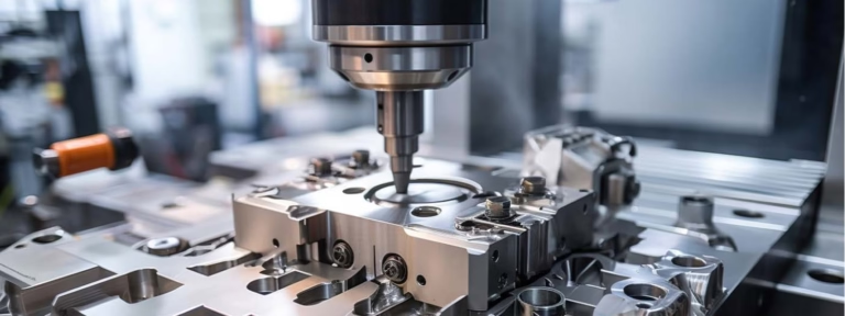
Operating a CNC router machine effectively is a cornerstone skill in modern workshops, bridging the gap between digital design and physical part. While the core principles of CNC machining remain consistent, mastering a router—often used for softer materials, composites, and woods—requires specific knowledge. For professionals in precision parts machining and customization, understanding this process is key to unlocking efficiency, repeatability, and complex geometric possibilities.
This guide will walk through the operational workflow, best practices, and critical considerations for running a CNC router, framed from the perspective of a manufacturing engineer in a high-mix, low-volume production environment like ours at GreatLight.
H2: Foundational Principles: What is a CNC Router?
Before touching the controls, it’s essential to understand the machine’s role. A CNC router is a computer-controlled cutting machine used for cutting various hard materials. It is typically used for 2.5D or 3D milling of:
Non-Metals: Woods, plastics (acrylic, PVC, polycarbonate), composites (carbon fiber, G10), foams, and modeling boards.
Softer Metals: Aluminum, brass, and copper are routinely machined on more robust industrial routers.
Signage, Prototypes, Fixtures, and Cabinetry.
Its operation revolves around translating a computer-aided design (CAD) model into a set of machine instructions (G-code) that control the movement of a spinning cutting tool along multiple axes (typically 3-axis: X, Y, Z).
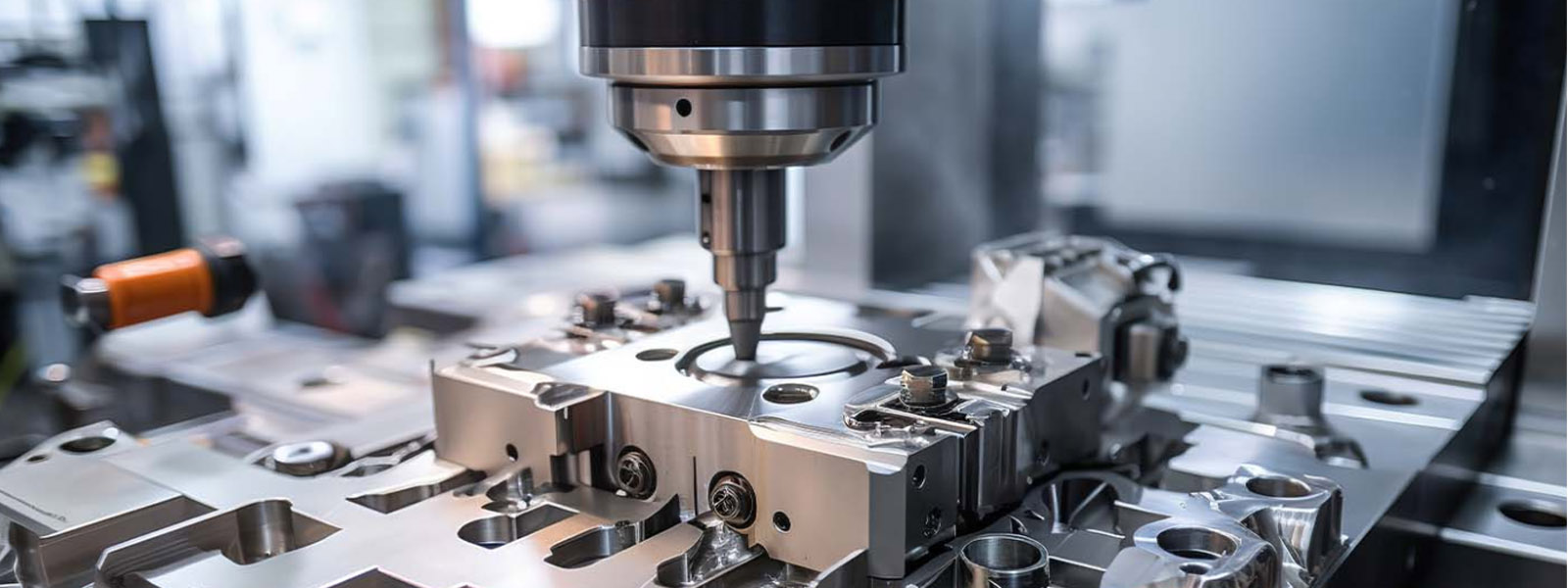
H2: The Step-by-Step Operational Workflow
Operating a CNC router is a systematic process. Skipping or rushing any step can lead to scrapped parts, tool damage, or machine collision.
H3: Phase 1: Pre-Machine Preparation & Design
CAD Model Creation: The process begins with a precise 3D CAD model of the part. Every feature—pocket, hole, contour—must be accurately defined.
CAM Programming: This is the critical engineering phase. Using CAM (Computer-Aided Manufacturing) software, the machinist:
Selects the stock material size and type.
Defines the Work Coordinate System (WCS): Establishes the X0, Y0, Z0 datum point on the stock.
Chooses Cutting Tools: Selects appropriate end mills, drills, or engraving bits based on material and feature geometry.
Creates Toolpaths: Strategically programs the router’s movement for operations like facing, pocketing, contour profiling, and drilling. Parameters like spindle speed (RPM), feed rate (IPM), and depth of cut are set here.
Generates and Simulates G-code: The CAM software outputs the G-code program. Always run a simulation to visually verify toolpaths, check for collisions, and ensure material is removed correctly.
H3: Phase 2: Machine Setup
Safety First: Don safety glasses, secure loose clothing, and ensure the work area is clean.
Material Securement: Fixturing is paramount. Use clamps, vacuum tables, or custom jigs to hold the stock material rock-solid. Any movement will ruin the part and tools.
Tool Loading: Install the required tools into the machine’s collets or automatic tool changer (ATC). Precisely measure and input each tool’s length into the machine control. This Tool Length Offset (TLO) tells the machine where the tip of each tool is relative to the spindle.
Setting Work Offsets: This aligns the digital program with the physical workpiece.
Use a probe or edge finder to locate the X and Y zero position on your stock.
Set the Z-axis zero, often by touching off the tool on the top surface of the material or a known fixture.
Input these values into the machine control as the Work Offset (e.g., G54).
H3: Phase 3: Running the Job
Program Load & Dry Run: Load the G-code program. Conduct a dry run (air cut) with the spindle off and the tool raised slightly above the material to verify travel paths and extents.
Initial Cuts: For the first part in a batch, consider using a reduced feed rate or cutting depth. Listen to the sound of the cut—a steady hum is good; screeching or chattering indicates a problem.
In-Process Monitoring: Monitor the first part closely. Check critical dimensions with calipers or gauges after key operations. Watch for chip evacuation—proper chips carry heat away; dust or melted material signals incorrect speeds/feeds.
Batch Production: Once the first part is verified, the router can run autonomously for the batch, but periodic checks are still advised.
H3: Phase 4: Post-Processing & Maintenance
Part Removal: After the cycle completes, safely remove the part, being mindful of sharp edges.
Deburring and Finishing: Router-cut parts often require manual deburring, sanding, or other secondary finishing.
Machine Cleanup: Remove all chips and dust from the work area, machine bed, and spindle. This is crucial for accuracy and machine longevity.
Basic Maintenance: Follow the manufacturer’s schedule for lubricating rails, checking belts, and ensuring the vacuum system (if used) is clean.
H2: Advanced Considerations for Precision Operations
For shops like GreatLight that handle high-precision custom components, especially when routing aluminum or precision plastics, additional rigor is applied:
Thermal Management: Even routers generate heat. For tight-tolerance work in metal, consider toolpath strategies that minimize heat buildup and use coolant or air blast if the machine is equipped.
Tooling Expertise: Knowledge of tool geometry (flute count, helix angle, coating) for specific materials dramatically improves finish quality and tool life. A 2-flute end mill is standard for aluminum, while a 3-flute might be better for finishing.
Fixturing for Complex Parts: For multi-sided machining (3+2 axis or true 5-axis indexing), designing and manufacturing precise custom fixtures is an engineering task in itself. This is where a partner with deep CNC machining expertise proves invaluable, as they can design and machine the fixture in-house.
Dust and Chip Control: Effective extraction is non-negotiable for part quality, tool life, and operator safety, especially with composites like carbon fiber.
Conclusion
Knowing how to operate a CNC router machine is more than just pushing start; it’s a disciplined integration of digital design, mechanical engineering, and practical workshop skills. It demands respect for the process, from meticulous CAM programming and rigid setup to vigilant monitoring. For businesses that require precision beyond basic woodworking or signage—such as functional prototypes, composite aerospace components, or intricate aluminum enclosures—partnering with a manufacturer that has systematized this operation to industrial standards is a strategic advantage.
At GreatLight, our operational protocols for CNC router machine and our broader 5-axis CNC machining centers are built on this rigorous, engineer-driven approach. We treat every job, whether on a router or a high-speed mill, with the same focus on precision, documentation, and traceability, ensuring that your custom parts are produced reliably and to specification, every time.
FAQ: Frequently Asked Questions
Q1: What’s the main difference between a CNC router and a CNC milling machine?
A: While both are subtractive manufacturing tools, routers are typically designed for larger bed sizes, faster speeds on softer materials, and often use a gantry structure. They may use router-style spindles. CNC mills are generally more rigid, built for higher cutting forces in metals, use slower-turning but more powerful spindles, and often have an enclosure with coolant systems. The line blurs with industrial-grade routers.
Q2: Can a CNC router achieve tight tolerances like a milling machine?
A: For materials it’s designed for, a high-quality industrial CNC router can hold tolerances within ±0.001″ to ±0.005″ (0.025mm to 0.127mm) under optimal conditions. For ultra-precision metallic parts with tolerances below ±0.001″ or complex 5-axis geometries, a dedicated 5-axis CNC machining center is the appropriate tool.
Q3: What is the most common mistake new operators make?
A: Inadequate workpiece fixturing is a leading cause of failure. A part that moves even slightly during cutting will be scrapped. Second is incorrect CAM programming, such as forgetting to set the correct Work Coordinate System or using overly aggressive feeds and speeds.
Q4: How important is the choice of cutting tool (end mill)?
A: Critically important. The material, number of flutes, coating, and geometry of the end mill must match the workpiece material and the type of cut (roughing vs. finishing). Using a wood-cutting bit on aluminum will fail immediately, and using the wrong flute count can lead to poor chip evacuation and heat buildup.
Q5: My design has a deep pocket. How should this be machined?
A: Deep features require multi-step “stepdown” toolpaths. Instead of trying to cut the full depth in one pass (which will break tools and produce poor finishes), the CAM program should be set to cut in successive layers (e.g., 0.5mm or 1xD of tool diameter per pass), allowing for chip clearance and reducing tool load.



















