In view of the difficulties in milling processing of air conditioning frames, a drilling auxiliary device and a method of use for controlling the precision of milling processing and reducing the surface roughness value are provided. Compared with the traditional milling method, this device adds a depth control and adjustment device, which can more precisely control the milling depth and improve the surface quality and efficiency of milling work.
01Preface
In some urban rail metro models, an air conditioning frame is designed in the roof structure to install the air conditioning unit. The mounting base of the air conditioning frame is generally designed with a U-shaped chute, and the air conditioning unit is. installed by installing a slider. The design of the air conditioning framework of a new subway project is different from this one. The basic mounting structure is a 15mm flat plate and requires processing of φ8mm conical countersink for subsequent installation of countersunk screws to fix the air conditioner and complete the installation of the air conditioner. the air conditioning unit.
The milling process is a mechanical processing method mainly used to process flat-bottomed or tapered countersinks on the surface of the workpiece opening. This process uses a specific cutting tool, a milling cutter, to fine-machine the hole to achieve the required shape and dimensional accuracy. The milling process is widely used in the manufacturing industry, especially where precise control of hole shape and size is required. Since manual milling cannot provide precise feed control, problems such as hole center deviation and poor surface quality are likely to occur, leading to large position errors and difficulties to ensure accuracy.[1,2 ]。
02 Milling process analysis and difficulties of air conditioning chassis
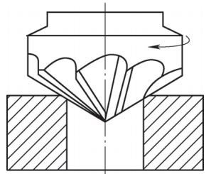
Air conditioning frame milling mainly involves processing taper milling after drilling is completed (see Figure 1), which requires high precision and is difficult to process. The operator uses a pneumatic drill equipped with a countersink (90° cone countersink, see figure 2) to directly countersink the through hole, which causes the following problems.
Figure 1 Countersunk hole

Figure 2 90° Taper Countersink Drill
(1) The machining precision is low, the pneumatic drill rotates very quickly, and the operator cannot control the wind speed well. The pneumatic drill cannot accurately guarantee that the milling cutter is perpendicular to the surface of the through hole during processing, resulting in. excessive coaxiality.
(2) The outer diameter of the counterbored hole is seriously out of tolerance. Since the operator cannot precisely control the amount of feed during the milling process, it is very likely that there will be too much milling or not enough cutting (see Figure 3a). , which could seriously damage the component.

a) First question b) Second question
Figure 3 Common Problems After Milling
(3) Low production efficiency In order to ensure that the depth is qualified during the milling process, the operator will measure the depth of milling several times, which will make it impossible to complete the milling work at one time and prolong the working time.
(4) When the surface quality of the countersink is very poor, polygonal vibration marks will be produced on the end face of the countersink hole (see Figure 3b). Since manual feed pressure cannot ensure continuous uniformity, the axial strength of milling. The hole will suddenly increase. If it is small, the cutting amount will be intermittent during cutting operations, and it will also react on the cutter, causing the cutter to jump, causing vibration marks, and making the surface of the countersink rough.
In short, due to the difficulty of processing, the operator must always be in a state of tension when drilling, which requires a high level of skill from the operator.
03Auxiliary device of drilling tool
Based on the actual working conditions and structural characteristics of the product, this article designs a milling auxiliary device. Compared with the traditional milling method, this device adds a depth control and adjustment device to more precisely control the milling depth and improve the surface quality. milling, thereby improving work efficiency.
3.1 Structure of the device and principle of operation
As shown in Figures 4 to 6, the device includes a limit device component to limit the drilling tool and operate along its fixed travel range; a positioning fixing component for limiting the position of the limit device component; a feed control component for controlling the limit; The feed rate of the drilling tool throughout the positioning device. The principle of operation is described below.

Figure 4 Schematic diagram of the device structure

Figure 5 Schematic diagram of limiting device and positioning components

Figure 6 Schematic diagram of power control component
1) When positioning and fixing the components, limiting the position of the limiter component can improve the precision of milling processing and ensure that the countersunk hole is coaxial with the original hole (the alignment method can be aligned with the human eye or the same as a countersunk hole bench drill) (centering method), so that the countersunk screws for subsequent installation can be driven vertically into the holes, making the appearance. neat and compact mounting location.
2) The feed control component can accurately control the depth of countersinking to ensure that the size of the processed countersink is consistent at the same time, it can reduce the surface roughness value of the inner wall of the countersunk hole and eliminate the generation ; vibration marks, which is more conducive to subsequent installation work.[3]。
3) This device is simple to use and operate, and can be installed on any pneumatic handle drill, reducing operator skill level requirements.
3.2 Introduction to use
As shown in Figures 7 to 11, limiting the position of the limiter component through positioning and fixing components can improve the precision of countersinking and ensure that the countersunk hole is coaxial with the original hole, so that the screw countersunk head can be inserted vertically. holes to make the appearance neat and the mounting position compact. The feed control component can accurately control the depth value of countersinking to ensure that the size of the counterbore processed is consistent at the same time, it can reduce the surface roughness value of the inner wall of the countersink, eliminate the vibration generation; Marks and correction of the counterbore position, which is more conducive to subsequent installation work.

Figure 7 Actual work clothing

a) Front b) Side
Figure 8 Introduction to Part 1 Functions

Figure 9 Introduction to Part 2 Functions

Figure 10 Introduction to Part 3 Functions

a) Pin connection b) Spring pressure shaft

c) Fixed block
Figure 11 Introduction to Part 4 Functions
The positioning fixing component and the power control component are respectively provided at both ends of the limiting device component. The limiting device assembly includes a device body, and a limiting groove is provided on the device body. The positioning and fixing assembly includes a fixed block, an adjustment rod, an adjustment handle and a top block provided with an adjustment hole. The adjustment rod is threaded with the adjustment hole. placed at both ends of the adjustment rod. The adjustment handle is located at the end opposite the main body of the device. Through the adjustment of the limit groove, the workboard can be placed there and clamped with the upper block, thereby realizing the clamping and positioning of the workboard.
The power control assembly includes an output connection block, a control rod and a connection rod; one end of the control rod is movably connected to the main body of the device, and the connection block is fixedly connected to the main body of the device; the fixed block is provided with a through hole for the passage of the connecting rod. One end of the connecting rod is connected to the middle part of the operating rod, and the other end passes through the through hole. It also includes elastic parts arranged between the control rods and a limiting block is arranged on the side opposite the control rods. Through spring adjustment, automatic reset of the operating rod can be realized, and adjustment of the limit block can avoid excessive reset (without adjusting the limit block, the connecting rod will appear at the center hole of the connection block when it bounces and resets, see Figure 9).
The connecting rod is connected to the control rod via an adjustment part; an adjusting bolt is provided on the side wall of the connecting rod, and a thread that matches the adjusting bolt is provided on the side wall of the connecting rod; placed in the connecting rod between the adjusting bolt and the upper connecting block. By adjusting the bolt setting, the spring elastic force and feeding depth can be easily adjusted. The through hole is a slotted hole. Through the oblong hole adjustment, different positions and forces can be easily adjusted and selected. The power control assembly includes a limiter having one end attached to the control rod, and the other end facing the limiter assembly. When using the control lever, since the control lever is pressed, when pressed to a certain extent, the limit element collides with the limit device assembly, thereby reaching the limit ( see Figure 10), providing control of the feed quantity. .
3.3 Display of the usage process
The usage process is shown in Figures 12 to 14.

Figure 12 Actual operational steps

Figure 13 Processing process

a) Finished product b) Test
Figure 14 The first step of post-processing inspection: after the through hole is processed, place the tooling in the corresponding position, and use the naked eye to observe that the pointer tip is facing the center of the hole, push all The grooves at the bottom of the air conditioning frame, once everything is complete, tighten the retaining knob built into the base.
Step 2: According to the processing depth required by the process, adjust the depth control nut and fix it.
Step 3: Place the pneumatic drill used to process countersink holes vertically into the tooling. Hold the air drill firmly with one hand and press the control rod down with the other hand. process the countersunk hole downward at a constant speed until it reaches the limit. The device works, stops the rotation of the air drill and lifts the pressure rod to reset it.
Step 4: Once treatment is complete, remove the device and place it in the next hole area to be treated. Place the M8 countersunk screw into the processed countersunk hole and check its processing accuracy and surface roughness.
04Conclusion
This solution limits the position of the limiter component by placing and fixing components, which can improve the precision of milling and ensure that the countersunk hole is coaxial with the original hole and the depth of milling can be precisely controlled through the power control component; ensure processing The size standard of the finished counterbore is consistent at the same time, it can improve the surface quality of the inner wall of the counterbore, eliminate the generation of vibration marks (see Figure 15), and correct the position of the counterbore. , which is more conducive to subsequent installation work. This device is simple to use and operate, and can be installed on any pneumatic handle drill, reducing operator skill level requirements. This solution can be applied to milling in other processes, filling the lack of precision control of manual milling in special parts.

a) Before improvement b) After improvement
Figure 15 Comparison of final effects
Daguang focuses on providing solutions such as precision CNC machining services (3-axis, 4-axis, 5-axis machining), CNC milling, 3D printing and rapid prototyping services.


