Traditional vertical machining centers generally only have milling functions, but for some parts requiring special processes, milling and turning functions are necessary. In response to this problem, a solution is introduced. On a vertical machining center, the servo spindle control function is used to add a rotation axis, which can serve as both an interpolation axis and an automotive spindle.
1 Preface
In the traditional machining process, multiple clamp and tool changes are required, which not only increases the machining time and cost, but also affects the machining accuracy. The composite milling and turning control of the vertical machining center can complete multiple processing steps in one clamping, thereby avoiding the problem of multiple clamping and tool changes and improving the processing efficiency and precision.[1-3]. Our company is equipped with a domestic well-known brand cradle turntable based on a vertical machining center. The A and C axis motors of the turntable are torque motors. The maximum speed of C-axis motor can reach 2000 rpm. The machine tool system of this machine is FANUC 0i-MF Plus (Type 1Type 1). The C axis must be additionally equipped with a servo motor-based spindle control function. This function can realize functions such as feed per revolution, threading, speed control, rigid tapping, actual spindle output speed and spindle indexing.
2 parameter settings
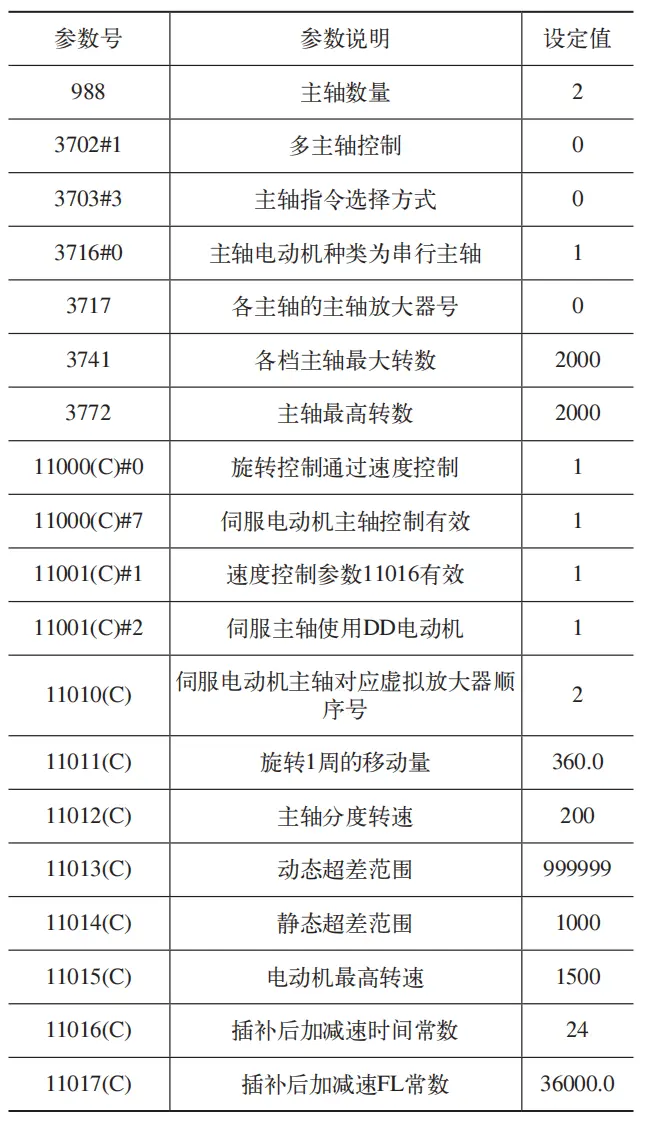
Fill in the servo motor spindle control parameters in the system, see Table 1 for details.
Table 1 System parameters
3 Preparing the ladder diagram
(1) Relevant signals mainly include G0027.1 (SWS2): second pin selection signal; G0029.6 (*SSTP): Spindle stop signal; G0027.4 (*SSTP2): Second spindle stop signal; 1.4 (SRVON5): SV rotation control mode signal; G0523.4 (SVRVS5): SV reversing signal; G0126.4 (SVF5): servo stop signal; F0010 (M): Auxiliary function code signal.
(2) Writing the ladder diagram first decodes M60 (C axis enters spindle mode) and M61 (C axis leaves spindle mode) through M code and gives instructions to R0644.4 and R0644.5 respectively (the R address can be set by yourself), as shown in Figure 1.

Figure 1 M60, decoding of M61 codes
Then enter the command from R0961.0 to R0644.4, form a self-lock, and finally output R0961.0 to G004.3 to complete the M code execution. This self-lock can be disconnected only by executing M61, or during a reset, emergency stop or alarm related to the C-axis. The diagram of the M60 locking scale is shown in Figure 2.

Figure 2 M60 lock
Decode M103 (car pin forward), M104 (car pin reverse) and M105 (car pin stop) via M code and give instructions to R0649.0, R0649.1 and R0649.2 respectively. The decoding of the car pin code is shown in Figure 3. Enter the commands to run and stop the pin in G0027.1, G0027.4, G0029.6, G0521.4 and G0523.4 through the address R and form a self-lock. G0027.1 automatically disconnects 80ms after self-locking, as shown in Figure 4; self-locking program G0027.4 is shown in Figure 5; self-locking program G0521.4 is shown in Figure 6; The program is shown in Figure 7 illustrated. The corresponding completion signal is output to G004.3 to complete the execution of the M code.

Figure 3 Decoding Car Pin Code

Figure 4 Self-locking program user G0027.1

Figure 5 Self-locking program G0027.4

Figure 6 Self-locking program G0521.4

Figure 7 Self-locking program G0523.4
When the C axis enters spindle mode, the C axis must be forcibly released, otherwise it may damage the C axis release mechanism and the generated powder may contaminate the encoder read head of the C axis. If the spindle rotation command is entered before executing M60, an alarm should be issued. The alarm number: “EX1043 Please enter rotation mode first” (the alarm number can be set by yourself) is used to remind the user. that M60 should be run in the current situation. If spindle rotation does not stop and F0376.4 is not set to 1, command M61 is executed and a user alarm is required. The alarm number is: “EX1046 fifth axis rotation does not stop, please do not exit rotation mode.”. In addition, some spindle temperature alarms are also necessary to ensure that the torque motor will not be damaged due to excessive temperature.
When reset, emergency stop, C-axis constant temperature oil tank alarm and C-axis temperature alarm occur in rotation mode, the spindle enable must be cut off and the servo stop signal G0126.4 (SVF5) must also be set. to 1.
(3) Changing the tool change program of the tool magazine Since the turning tool needs to be fixedly placed, the handle of the turning tool is equipped with a locating pin and the box spindle is equipped with a corresponding locating pin hole, so that the turning tool can be fixed. It also needs to be positioned. Install a proximity switch near the pinhole to confirm whether the turning tool is installed on the spindle. If the turning tool is on the spindle, the turning tool confirmation signal is 1. The installation of the turning tool is shown in Figure 8.

Figure 8 Turning tool installation diagram
The tool magazine capacity of our company’s vertical machining center is 20 tools, and tools No. 16 to No. 20 are defined as turning tool numbers. When the current spindle tool is a turning tool, the first spindle activation is canceled and. G0027.3 is forcefully set to 0, forcing the spindle not to rotate. First, determine whether the current tool number of the spindle is ≥16. If ≥16, set R0900.0 to 1. At this time, you can determine whether the spindle is a turning tool, as shown in Figure 9. Since the spindle needs to be stopped directionally when the manipulator changes tools to ensure that the key of the spindle end face and the groove of the tool holder do not collide, so if the front tool of the spindle is a turning tool, the precise stop command of there spindle should be ignored when executing the tool change command. To resolve this issue, first connect the coil from G0055.0 to R0900.0 which corresponds to #1008 in the processing program. When G0055.0 is set to 1, #1008 is also set to 1, as shown. in Figure 10 shown. Then replace M19 with “IF[#1008EQ1]GOTO6;M19;N6;”, when there is a turning tool on the spindle, the program will skip M19.

Figure 9 Program to determine if the tool is a turning tool

Figure 10 G0055.0 corresponds to #1008 in the processing program
If the current tool number of the spindle is a turning tool, but after the turning tool is manually removed, the turning tool confirmation signal is 0 at this time, then the position Current stop of the spindle may not be at the precise stop position due to manual rotation. Therefore, when performing the tool change action, the spindle orientation command will be ignored and the tool holder may collide with the spindle, causing the machine tool to fail. Therefore, in this case, a user alarm is issued: “EX1047 Please install filming”. the tool on the spindle. Then carry out the tool change procedure” to avoid unnecessary breakdowns.
When everything is ready, add G33IP_F_ (F is the pitch of the vertical axis) to the processing program to perform equal pitch cylindrical threading.
4 Conclusion
By applying the compound function of milling and turning to the machining center machine tool equipped with FANUC system, it avoids multiple clamping of the workpiece and meets the requirements of processing technology. It can improve processing efficiency, reduce costs and improve accuracy. suitable for processing different types of parts. Processing requirements are one of the very important technologies in the field of modern machine manufacturing. The practical application areas are very broad and can play an important role in many industries.
Daguang focuses on providing solutions such as precision CNC machining services (3-axis, 4-axis, 5-axis machining), CNC milling, 3D printing and rapid prototyping services.


