Considering the large size, high precision and easy deformation characteristics of the large gear of the crusher, combined with many years of processing experience, the whole processing process has been improved. The turning and milling process is carried out by combining the two halves and coupled processing. The casting and processing constraints of the large gear are eliminated through “three turning and two milling” and artificial aging, which solves the processing problems of these parts.
1 Preface
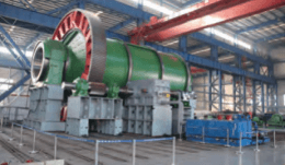
At present, grinders are widely used in various industries[1,2]. Figure 1 shows the ball mill test. The big gear is the main part of the overflow ball mill. The common structure is to use two sets of 1/2 gears in pairs. This article takes a 5°15′ straight helical gear as an example.
Figure 1 Ball mill test
2 process points
Figure 2 shows a large gear. Among its gross dimensions, the most critical dimension is the rim wall thickness. It is necessary to measure and monitor the degree of gear deformation and rim tolerance repeatedly before and during processing. Since a large part of the material is removed during processing, significant cutting stresses will be generated (mainly in rough turning and milling processes). The stress release problem must therefore be taken into account and the amount of deformation after stress release must be minimized (the impact entering the virgin material must be with stretching).

Figure 2 Large gear
The material of large gears is mainly ZG35, but also includes ZG35SiMn, ZG42CrMo, etc. It must be quenched and tempered to achieve the predetermined strength. There are also defect detection requirements, which generally correspond to level II of ultrasonic defect detection in JB/T. 5000.9-1998. The order of packaging and fault detection should be arranged reasonably.
The structural forms of the two-piece half-wheel connection include pin positioning (also known as “dumbbell pin”), reamed hole bolt positioning, and threaded taper pin positioning. The locating pin holes must all be machined simultaneously and before finishing. The axis of the barbell pin hole should be on the joining surface of the two half wheels and should be as perpendicular as possible to the upper end surface of the gear. Ensure the concentricity requirements of the outer circle of the large gear, the index circle and the circles of the inner flange (including the position accuracy of the mating hole of the inner flange), the outer circle of the large gear, the gear end face (tooth width direction) and the verticality requirements of the inner flange mating surface. This requires the correct selection of process references[3,4]. The joint surface of the two half gears includes a straight joint surface, an oblique joint surface and multiple empty cuts. When final closing, the local deviation of the straight joint surface should be <0,1 mm et l'écart de la surface du joint oblique est >0 and <0.5 mm. When processing the joint surface, it is necessary to avoid the "large and a half" situation of the half wheel, and at the same time, the processing order of different empty tools should be considered (note that the bottom of the empty tool groove between the straight joint surface and the oblique joint surface is a bevel).
3 Half gear processing technology
The processing process of half gears is as follows.
1) Step 01: Draw lines. Place the workpiece flat on the marking platform, place three square boxes of the same height on it, and comprehensively consider the symmetry of the tooth width, inner flange thickness and height of the two surfaces joint, use a jack to adjust the level and place it in half. A horizontal alignment line (called a “flat line”) is drawn on the outer circle of the gear. Determine the center of the half gear according to the uniformity of the inner wall thickness of the rim (untreated surface), draw a perfect circle line on the upper surface of the half gear, and draw the processing line of the joint surface (straight joint surface and joint surface inclined at 5°15′). Finally, drill two or three holes in the ends of each wire. It is necessary to record the rim wall thickness data in detail and report it to the technical staff. If the wall thickness is out of tolerance, repair will be necessary.
2) Process 02: Rough boring. Place the half-gear shown in Figure 3 flat on the square box of equal height, facing the head of the bed. Align according to the flat line and the processing line of the joint surface, control the alignment deviation within ±0.5mm and tighten firmly. Roughly countersink the straight joint surface and the empty grooves of the tool at both ends, leaving 6mm on each surface. Then mill two small sections below the two joint surfaces to align the base surface. The surface roughness value of each machined surface is Ra=6.3 μm. Raise the 90° position of the half gear so that its flat line forms an angle of 5°15′. Use the Alignment Base Surface, Straight Joint Surface and Angle Ruler to make the straight joint surface have a bevel angle of 5°15′. Press the piece firmly. Roughly mill the surface of the oblique joint at one end, leaving 6 mm on one side, and the surface roughness value Ra = 6.3 μm. Lift both ends of the half gear mating surface so that its flat line has a bevel angle of -5°15′. The clamping and alignment method is the same as above, and the other inclined joint surface is roughly countersunk, leaving 6mm on one side, and the surface roughness value Ra = 6.3μm.

Figure 3 Half gear
3) Step 03: Draw lines. Align according to the circular and flat lines of the large gear (you can go to the machine tool to draw the line), draw the processing line for each hole on the joint surface, and drill the center of the hole.
4) Process 04: Rough boring. Lay the gear half flat with the gasket facing the head of the bed. Drill holes on each joint surface leaving 6-8mm on each side. The back of the hole is countersunk. The surface roughness value of each surface is Ra = 12.5 μm.
4 sets of post-processing technologies
Due to the large mass of the large machine, be sure to pay attention to safety when lifting it. After finishing, protective measures should be taken when lifting to avoid damage to the treated surface. The processing process of the assembled large gear is as follows.
1) Process 01: Clamps. Align the two half gears according to the flat and round lines, hold them together with process bolts, and weld the welding block firmly on the untreated surface above the joint surface. The butt welding position of the half gear is shown in Figure 4. Pay attention to the position of the air hole when welding the weld block.

Figure 4 Illustration of half gear welding position
2) Step 02: Draw lines. Place the large gear flat on the marking platform, place three square boxes of the same height on it, refer to the original flat line of the half gear, and use a jack to level it. Based on the joining surface of the two half-wheels and taking into account the uniformity of the inner wall of the rim, determine the center of the large gear. Draw horizontal alignment lines (called “flat lines”), top and bottom end face processing lines, and outer circle processing lines (called “round lines”) on the outer circle and top surface in sequence, and drill two or three holes at the ends of each line. Check whether the joint surface thickness and spoke thickness of the wheel meet the drawing requirements and whether the tie bars affect the fit of the gears. The markings on each point of the large gear are shown in Figure 5. The thickness at A, I, B and H is greater than 60mm, and the thickness at C, G, D, E and F is greater than 50mm. are marked on the back of the spokes. The thickness of each spoke on the thick side is greater than 95mm, and the value is marked on the back of the spoke.
3) Process 03: Rough turning (processing each surface to prepare for flaw detection and quenching). Access the inner reverse clamp flange of the vertical lathe (you can determine whether to add a claw holder based on the width of the gear), use a jack to adjust the level, and use a marking disc to check the horizontal line so that the horizontal deviation is ±1mm. Then adjust the chuck claws, attach the scribe needle to the tool holder, and check the round line to make the workpiece and the rotary table concentric, and the concentricity deviation is ±1mm. Clamp and press the workpiece firmly, then machine the flat surface and the outer circle in sequence, leaving 20mm on one side. Then use a counter mill to rotate a 20mm wide annular reference plane under the gear. The surface roughness value of the outer circle is Ra=3.2 μm and the surface roughness value of other surfaces is Ra=6.3 μm (the inner surfaces of the flange are not processed at this time). Rotate the workpiece 180°, clamp the outer circle, and align the outer circle and the ring of the upper end surface as the reference plane, with a deviation of ±0.5mm. Roughly turn the surface, leaving 20mm on one side and surface roughness. Ra value = 6.3 μm. Each edge and corner is blunted to 3mm × 45° to prevent cracking during quenching.

Figure 5 Markings of different points on the large gear
4) Process 04: Clamps. Separate the two gear halves.
5) Process 05: Defect detection (checking internal defects of the material). According to the technical requirements of the drawing, carry out ultrasonic flaw detection on the outer circumferential surface of the large gear.
6) Process 06: Finishing (repair of blank defects). The appearance of the blank is refined, and the defective parts that exceed the standard are refined (defect cleaning, repair, welding and polishing). After passing the re-inspection, the following process is carried out.
7) Process 07: Inspection. Check the chemical composition and rationality of distribution of the material. Use an electric drill to take approximately 50g of chips each from the 30°, 90° and 150° positions on the non-rising side of the gear and at the riser (note that the manufacturer is required to mark the position of the riser on the opposite side of the gear). workpiece). There should be no oil stains on the chips. Use paper. Pack the gear in a bag and mark the production number, drawing number, step number and casting number of the gear on the paper bag. Send the samples obtained from the gear to the physical and chemical laboratory to test the chemical composition, compare the test results with the standards, and compare the composition of each point of the same equipment to see if it is within the standard range. After meeting the requirements, proceed to the next process and return the ingredient list to the heat treatment company.
8) Step 08: Draw lines. Double-check the size of the blank and note the thickness of the radius. Use the processed outer circle and end face as a tracing reference, check the machining allowance of each part by tracing, and check the radius thickness by comparing it with the marked value.
9) Process 09: Quenching and tempering treatment (improvement of mechanical properties). Figure 6 shows the quenching and tempering treatment of the half gear to make the hardness meet the technical requirements of the model.
10) Step 10: Pliers. Remove the constraint and machine the flange. Cut the ties with a gas cutter and store them properly.

a) Half-gear furnace heating

b) Half gear quenching
Figure 6 Quenching and tempering treatment of a half gear
11) Step 11: Draw lines. Check the deformation of the blank. The part should be placed flat and the alignment method is in step 02. Use the end face of the gear (in the direction of the tooth width) as a rough reference for leveling. Determine the center of the half gear based on the uniformity of the inner wall thickness of the rim and the hole spacing on the two mating surfaces. According to the heat treatment deformation, consider the uniformity of the machining allowance everywhere, draw the whole line, draw the alignment line, and draw two small sections of circular alignment lines on the upper plane of the half gear (at the joint surface). Mark the straight joint surface and the 5°15′ oblique joint surface processing lines as well as the blank tool groove processing line. Drill two or three holes in the end of each wire. Check the thickness of the spokes, check whether the joint surface and its adjacent surfaces as well as the transition fillets are widened and mark them. Note that if the distance between the joint surface exceeds 10mm, the process should be suspended and repaired.
12) Process 12: semi-finished boring. Place the half gear flat on the square box of the same height, facing the headboard. Align according to the flat line and the processing line of the joint surface, control the alignment deviation within ±0.5mm and tighten firmly. Semi-finished milling of the straight joint surface and empty tool grooves at both ends, with a margin of 3mm on each surface and a surface roughness value of Ra=6.3μm. Mill two small sections below the two joint surfaces to align the base surface. Raise the 90° position of the half gear and use the alignment base surface, straight joint surface and angle ruler to make the right joint surface have a bevel angle of 5°15′. Press the workpiece firmly, semi-finely mill the oblique joint surface at one end, leaving 3mm on one side, and the surface roughness value Ra = 6.3μm. Lift both ends of the half gear mating surface so that the right mating surface has a bevel angle of -5°15′. Semi-mill the other oblique joint surface, leaving 3 mm on one side, and the surface roughness value Ra = 6.3 μm. Note that when processing the oblique joint surface, the knife should be cut at the longitudinal center line so that the center of the oblique joint surface is 0.25mm lower than the center of the joint surface right.
13) Step 13: Draw lines. Align the outer circle and the top plane of the half gear (you can access the machine tool to mark the line) and draw the processing lines for each hole on the joint surface. Note that when drawing the hole machining line of the joint surface, the quenching and deformation of the gear should be considered, and the hole position can be adjusted appropriately to make the two consistent halves of the gears.
14) Process 14: Boring. The piece is laid flat with the joint facing the head of the bed. Drill holes on the joint surface leaving 3 to 4 mm on each side. The back of the hole is countersunk. The surface roughness value of each surface is Ra = 12.5 μm.
15) Step 15: Pliers. Finish the joint surface of the two half wheels, clean the burrs, burrs and dirt, etc., and align them according to the round line and flat line, with a tolerance of ±0.5mm. Use process bolts to connect the two half gears, and the gap between the direct joint surfaces should be <0.2mm. Tap the head on the untreated surface of the top end of the gear and weld the welding block onto the untreated part of the joint. Note that during assembly, you should carefully check the half gear pattern to confirm whether there are any asymmetrical design elements such as inconsistent sizes of the upper and lower rims, uneven distribution of ram seats (cylinder holes). cylinder screw), etc., to avoid assembly. errors.
16) Step 16: Draw lines. The part should be placed flat and the alignment method is in step 02. Based on the joint surface of the two half wheels and taking into account the uniformity of the inner wall of the rim, determine the center of the large gear. Draw flat lines, outer circle processing lines, and upper and lower end face processing lines, and drill two or three holes at the ends of each line. It is necessary to record the rim wall thickness data in detail (take 10 points on the circumference) and report it to the technical personnel. If the wall thickness is out of tolerance, the process will be suspended and repaired.
17) Process 17: Semi-finish turning (to serve as a reference for rough milling of gears). Use a vertical lathe to tighten the inner wall of the rim, use a jack to adjust the level, and use a marking disc to check the horizontal line so that the horizontal gap is ±0.5mm. Then adjust the chuck claws, attach the scribe needle to the tool holder, and check the round line to ensure that the concentricity deviation between the workpiece and the rotary table is ±0.5mm. Clamp and press the workpiece firmly, then semi-finish the flat surface, outer circle and inner hole, end face and adjacent notch of the inner flange, leaving 10mm on one side and the value of surface roughness Ra = 3.2 μm. Then use the reverse tool to rotate the plane under the inner flange to create a 20mm wide annular reference plane. The part is rotated 180° and the outer circle is tightened. The outer circle and the top plane of the inner flange are used as a reference for alignment. The deviation is ±0.1mm. The upper plane of the semi-finished rotating mechanism and the upper plane of the inner flange are left 10 mm to one side. . The surface roughness value is Ra=3.2 μm. Draw a 60° V-shaped circular line at the index circle of the tooth tip, 1 mm deep.[5]。
18) Process 18: Defect detection. Perform ultrasonic flaw detection on the entire outer circle of the large gear according to the technical requirements of the drawing, paying particular attention to the presence of cracks.
19) Process 19: Rough milling of teeth. Adjust the position of each bracket on the workbench in advance so that the outermost end of the bracket is slightly smaller than the size of the root circle of the large gear. The end of the large gear with the V-shaped engraved line should face upward and lie flat, and use a dial indicator to detect the upper plane (axial circular voice <0.5mm). Use a jack to hold the tool holder and the outer circle of the gear respectively, then use a dial indicator to check the outer circle and adjust the concentricity of the large gear and the rotary table (round circular radial <0.5 mm). After passing the test, press the part firmly. Place the knife at the joint seam and carve the knife in two places (it is necessary that the flower of the knife is consistent from top to bottom, and the joint seam is in the middle of the tooth groove). Rough milling of teeth, leaving 10 mm on one side, surface roughness value Ra=6.3 μm. Note that before milling the teeth, you should check the outer circumference of the gear and whether the position of the index circle markings is correct, to determine the depth of the rough milled teeth. After the teeth are milled, the quality inspector should visually inspect whether there are cracks and other surface defects in each tooth groove.
20) Step 20: Pliers. Disassemble the two halves of the gear and weld the fasteners. Since the inner flange was roughly machined, the tie rods are not long enough. The tie rods can be moved appropriately in the 90° direction of the half gear, or the processing steel plate can be connected (using continuous fillet welds with a weld). height of 15 mm). Note that this process does not need to be performed for large gears with a diameter of ≤8000mm.
21) Step 21: Heat treatment. Artificial aging. The workpiece should be leveled with pads of the same height and the number of support points is ≥4. Note that when the diameter of the workpiece is ≤8000mm, it should be put into the oven for aging.
22) Step 22: Pliers. For a large gear aged as a whole, divide it into two halves; if it is an aged half gear, the link bars need to be cut. Use a steel brush and rust remover to clean the grooves of each rough milling tooth so that the quality inspector can visually detect whether there are cracks in the grooves. Note that if suspected cracks noted by the quality inspector cannot be confirmed by further polishing and cleaning, they can be confirmed by staining and defect detection.
23) Step 23: Draw lines. Check the deformation of the part after heat treatment. The center of the half gear is determined according to the joint seal and the circle of the tooth tip, and taking into account the uniformity of the rim wall thickness. Then draw the processing line of the joint surface (the processing margin should be as small as possible). Note that when the maximum depth difference of each tooth groove is >3mm or the machining allowance of the joint surface is >3mm, the process should be suspended and the technician should be notified to handle it.
24) Process 24: Boring. Place the workpiece flat, align it according to the flat line and the treatment line of the straight joint surface, and press firmly. The alignment deviation is ±0.5mm. The direct mating surface of the half gear is finely milled until it meets the design requirements (it only needs to be flat). At the same time, each empty tool step on the direct joint surface must be processed until it meets the design requirements). , and the X and Y directions are milled on the upper plane of the positive belt, length ≥400mm. Lift the 90° position of the workpiece and the positions of the two joint surfaces in turn, so that the straight joint surfaces are at bevel angles of 5°15′ and -5°15′ respectively, and process the oblique joint surfaces and empty them. tool grooves. Note that the alignment method for each step in this process can be referred to Process 12.
25) Step 25: Draw lines. Align the outer circle and the upper plane of the half gear (you can access the machine tool to mark the line) and draw the processing and inspection lines for each hole on the joint surface.
26) Process 26: Boring. Align according to the flat line and the joint surface, drilling each joint hole and milling the back surface to meet the drawing requirements.
27) Process 27: Tightening (both halves of the gears are rounded precisely). Finish the joint surface of the two halves of the wheel (see Figure 7), clean the burrs, burrs and dirt, etc., and align the joint surface according to the prefix. Then align the round lines and flat lines and control the gap to ±0.5mm. Use product bolts to connect the two half gears. The gap between the direct joint surfaces should be <0.1mm and weld the process welding block to the untreated part of the joint.
28) Step 28: Set the dowel holes. Mark two processing lines for the pinholes (barbell pin mounting holes).

Figure 7 Finishing the joint surface of the two wheel halves
29) Process 29: Boring. Place the workpiece flat, press the alignment belt above the joint surface to find the level, the tolerance is ±0.02mm/100mm (the alignment distance should be as large as possible ) and press firmly. Use a right angle milling head to drill and enlarge two pin holes and concentric counterbores to meet design requirements. Be careful not to process the pin holes half size. After processing, the unfit surface near the hole should be tapped and marked A and B to facilitate pin preparation.
30) Process 30: Gripper (assembled into a whole large gear). Disassemble the gear and install it into the pin, then reassemble it. When checking the gap with a feeler gauge, the 0.05mm feeler gauge does not fit. Use the studs and nuts on the product to hold it securely. The inspection department passes the inspection, makes a registration and marks the corresponding mark on the prefix. Note that during disassembly and reassembly before completing turning or milling, the gap between the mating surfaces should be checked and recorded.
31) Process 31: Marking (confirmation of alignment and processing standards). Draw the cross center line based on the joint seam and draw each circle and end face treatment line.
32) Process 32: Finishing turning (reference for fine gear milling and installation alignment). Use a vertical lathe to reversely block the inner wall of the rim and align it with the flat line and the round line in sequence, with a deviation of ±0.5mm. Tighten and press the part firmly. The flat surface, the outer circle, as well as the inner hole, end face and adjacent stop of the inner flange are semi-finished in sequence until they meet the requirements of the drawing and the value of surface roughness Ra=3.2 μm. Then use the reverse tool to rotate the plane under the inner flange to create a 20mm wide annular reference plane. The part is rotated 180° and the outer circle is tightened. The outer circle and the upper plane of the inner flange are used as a reference for alignment, with a deviation of ±0.1mm. The upper plane of the gear and the upper plane of the inner flange are finely turned to meet the design requirements. and the surface roughness value Ra = 3.2 μm. A 60° V-shaped circular line is rotated at the index circle of the tooth end face, with a depth of 1 mm. Note that the alignment method for each step in this process may refer to the semi-finishing turning process.
33) Process 33: Milling the teeth (see Figure 8). Line up the outer circle and the lower end face (the side without etched lines at the end of the tooth) as a reference. After the axial circular runout and radial circular runout meet the drawing requirements, press the workpiece firmly.[6]. Calculate the tool according to the original tooth groove, and use the joint surface of the two half wheels as the center of symmetry (the tooth surfaces on both sides of the joint joint should be uniform) and finely mill the teeth until they meet the design requirements.
34) Step 34: Draw lines. Place the workpiece flat and use the inner hole of the inner flange as a reference to mark the inner flange handle closing hole processing line, inspection line and screw hole processing line on the stop, use the circle of the tip of the tooth or its concentric circle; the standard to mark the screw hole processing line on the tooth side and check the line and drill holes in the center of each hole.

Figure 8 Processing of milling gears
35) Process 35: Drilling. Place the workpiece flat, press it firmly, drill the inner flange handle hole, and pre-drill the pre-holes for the screw holes on the end face of the reamer to meet the drawing requirements. Note that before drilling, you should check whether the marked hole spacing meets the requirements of the drawing, and then use the punch sample to align the original punch hole and press to enlarge it. For larger diameter holes, the pre-holes must first be drilled with a small size drill bit. Only after determining that each pre-hole is concentric with the inspection line can it be drilled and enlarged to the size of the pattern.
36) Step 36: Pliers. Use a universal drill to drill the radial screw holes and tap the screw holes on the gear end face. Realign the gear, check the clearance on the joint surface and record it. After the overall inspection is passed, the two halves of the gears are dismantled, and the head is tapped on the untreated surface near the joint surface (or the head is tapped after spot welding the special steel plate), then subsequent assembly, painting and packaging are carried out (see photo) 9) and other processes.

Figure 9 Half-gear packaging
5Conclusion
The large grinder gear in this item has the characteristics of large size, high precision and close fit. The difficulty is that the stress is concentrated after the parts are processed and they are easy to deform. Through process improvement, we formulated a process route to combine the two halves and overall processing, and adopted the “three turning and two milling” and artificial aging methods to eliminate the constraints of casting and processing, solve the processing and deformation problems of large gears, and provide a good basis for the production of such parts. Manufacturing provides a reference.
Daguang focuses on providing solutions such as precision CNC machining services (3-axis, 4-axis, 5-axis machining), CNC milling, 3D printing and rapid prototyping services.


