

The Engine of Form: Demystifying the CNC Bending Machine in Precision Fabrication
In the intricate world of precision parts manufacturing, where flat sheets of metal are transformed into complex, three-dimensional components, one piece of equipment stands as a master of controlled deformation: the CNC bending machine. For clients seeking custom metal enclosures, chassis, brackets, or any formed sheet metal part, understanding how a CNC bending machine works is key to appreciating the engineering marvel that brings your designs to life with repeatable accuracy. This process is a cornerstone of modern sheet metal fabrication, bridging the gap between digital designs and physical, functional hardware.
At its core, a CNC (Computer Numerical Control) bending machine is a press brake that has evolved from manual, skill-dependent operation into a highly automated, software-driven system. It doesn’t cut material away; instead, it precisely folds it along predetermined lines. For manufacturers like us at GreatLight Metal, mastering this technology is integral to delivering the seamless, one-stop manufacturing solutions our clients rely on.
The Basic Working Principle: Force, Die, and Punch
The fundamental physics are straightforward. A CNC bending machine clamps a sheet of metal between a matching set of tools: a punch (the upper, moving tool) and a die (the lower, stationary tool with a V-shaped, U-shaped, or specialized channel). The CNC system drives the punch downward with immense force, forcing the sheet into the die’s opening and causing it to plastically deform—bend—along the line of contact.
The critical variables controlled by the CNC are:
Bend Angle: Determined by how deep the punch penetrates the die.
Bend Position: Precisely located along the X and Y axes of the sheet.
Bend Sequence: The intelligent order of operations to avoid tool collisions and material springback interference.
A Step-by-Step Journey Through a CNC Bending Cycle
Step 1: Digital Blueprint & Programming
The process begins far from the shop floor. The client’s 3D CAD model (often a .STEP or .IGES file) is imported into specialized bending simulation software. Here, the part is digitally “unfolded” into a flat pattern. A skilled programmer then determines the optimal bending sequence, selects the appropriate punch and die tools from the machine’s library, and calculates all necessary parameters, including compensation for material springback—the metal’s natural tendency to slightly rebound after bending. This program is then uploaded to the machine’s CNC controller.
Step 2: Machine Setup & Tooling
The operator installs the specified punch and die sets on the machine. Modern CNC press brakes often feature automatic tool changers or segmented tools that can be configured for different bend lengths without full changeovers, drastically reducing setup time. The back gauge—a programmable fence that positions the sheet—is calibrated.
Step 3: Material Positioning & Clamping
The sheet metal blank, often laser-cut or punched in a previous operation, is placed against the back gauge, which positions it with micron-level accuracy for the first bend. A hydraulic clamping beam (the upper beam) descends to securely hold the sheet in place against the die, preventing slippage during the bending process.
Step 4: The Precision Bending Stroke
The CNC executes the programmed command. The ram, equipped with the punch, descends with controlled force and speed. The sheet metal is forced into the die cavity. For air bending (the most common method), the punch does not bottom out in the die, allowing a single set of tools to achieve multiple angles based on penetration depth. The machine’s precision is ensured by synchronized servo-electric or hydraulic drives on both sides of the ram, preventing tilt and ensuring a consistent bend along the entire length.
Step 5: Release, Reposition, and Repeat
After reaching the target depth, the ram retracts. The workpiece is then released, repositioned by the back gauge or a robotic arm for the next bend, and the cycle repeats until the complete part is formed. Modern machines may use laser angle measurement systems to check each bend in real-time and make automatic corrections, ensuring consistent quality across a production run.
Key Components That Enable Precision
CNC Controller: The brain of the operation. It interprets the program and coordinates all movements of the ram, back gauge, and ancillary equipment.
Ram/Beam: The moving component that carries the punch. Its parallelism and deflection control are critical for uniform bends.
Back Gauge: A multi-axis, programmable stop that positions the sheet. Advanced gauges can have multiple fingers to support complex, multi-flange parts.
Tooling (Punch & Die): Made from hardened tool steel, these come in myriad shapes and sizes to create different bend radii, geometries, and hemming operations.
Crowning System: Often a CNC-adjusted system that slightly arches the bed or die to compensate for machine deflection under load, ensuring a perfectly straight bend across long parts.
Why CNC Bending is a Game-Changer for Custom Parts
Extreme Accuracy and Repeatability: Once programmed, a CNC press brake will produce the first part and the thousandth part with identical precision, often within ±0.1° or better. This eliminates the variability inherent in manual bending.
Complexity Made Simple: It can handle intricate bending sequences with multiple angles and flanges in close proximity that would be impossible or highly inefficient to produce manually.
Speed and Efficiency: Automated programming, quick setup changes, and fast cycle times accelerate prototyping and production runs.
Material Versatility: From thin, delicate aluminum to thick, high-strength stainless steel, CNC machines can be configured with the appropriate tonnage and tooling to handle a vast range of materials.
Reduced Physical Labor and Skill Gap: The CNC system encapsulates the bending expertise, reducing reliance on highly specialized manual brake operators and making advanced fabrication more accessible.
Applications in Modern Industry
The reach of CNC bending is universal in precision engineering:
Enclosures & Cabinets: For servers, medical devices, industrial controls.
Structural Components: Brackets, frames, and supports in automotive, aerospace, and robotics.
Consumer Products: Housings for appliances, fitness equipment, and electronics.
HVAC & Ductwork: Complex air handling components.
Conclusion: More Than Just a Bend
Understanding how a CNC bending machine works reveals it as a sophisticated synthesis of mechanical force, material science, and digital intelligence. It transforms static sheets into dynamic, structural components that form the skeletons of modern technology. For clients, partnering with a manufacturer that leverages this technology within a full-process ecosystem—from design support and precision cutting through bending to finishing—is crucial. At GreatLight Metal, our advanced CNC press brakes are not standalone tools; they are integrated nodes within our comprehensive manufacturing solution, ensuring that every bend contributes to a part that meets the highest standards of precision, consistency, and performance. It is this holistic command over processes like precision 5-axis CNC machining services and CNC bending that allows us to be a true engineering partner, turning complex design challenges into manufactured realities.
Frequently Asked Questions (FAQ)
Q1: What is the difference between a CNC press brake and a manual press brake?
A: A manual press brake relies entirely on the operator’s skill to set bend depth, position the material, and apply force. A CNC press brake uses a computer program to automate and control all these parameters with extreme precision, ensuring repeatability, handling complex jobs, and requiring less specialized manual skill for operation.
Q2: What is “springback,” and how does the CNC machine compensate for it?
A: Springback is the elastic recovery of metal after bending, causing the final bend angle to be slightly more open than the angle achieved during the pressing stroke. CNC machines compensate through overbending. The bending program is calibrated to drive the punch slightly deeper than the target angle, so when the material springs back, it settles exactly at the desired angle.
Q3: What file format do I need to provide for CNC bending?
A: The ideal starting point is a fully defined 3D CAD model (e.g., .STEP, .IGS, .SLDPRT). This allows the manufacturer to generate the flat pattern, simulate the bend sequence, and identify any potential manufacturability issues. Detailed 2D drawings with bend lines and angles are also acceptable but provide less information for optimization.
Q4: Are there limitations to the complexity of shapes achievable with CNC bending?
A: While incredibly versatile, limitations exist. Very small, internal flanges might not be reachable by standard tools. The minimum distance between two bends (flange length) is constrained by the size of the punch and die. Additionally, certain geometries may require a specific bending sequence to avoid tool collision, which an experienced programmer will determine.
Q5: How does a manufacturer like GreatLight Metal ensure bending accuracy for high-volume orders?
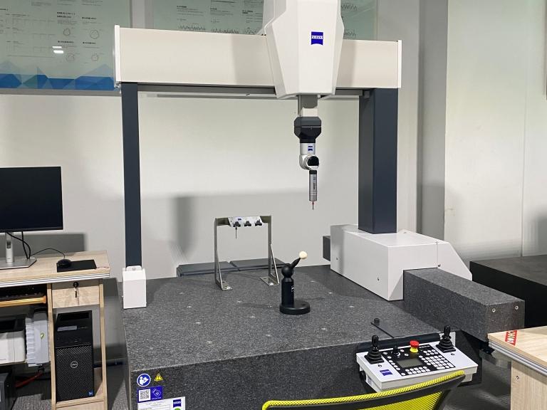
A: We employ a multi-faceted approach: First, we use high-end CNC machines with real-time angle measurement and correction systems. Second, we conduct thorough first-article inspections using coordinate measuring machines (CMM) to validate the programmed part. Finally, our ISO 9001-certified quality management system mandates in-process checks at defined intervals throughout the production run to monitor and maintain consistency. You can learn more about our professional network and industry engagement on platforms like LinkedIn.



















