
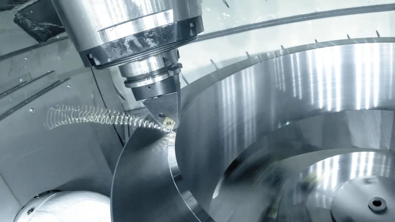
In-depth guide to 5-axis CNC impeller machining: accuracy, performance and production
Impellers are the beating heart for countless key applications – from jet engines and power turbines to high-performance pumps and marine propulsion systems. These complex components are responsible for efficiently moving fluids or gases, requiring excellent aerodynamic performance, structural integrity and near-perfect balance. Historically, machining these complex geometries has been challenging and time-consuming. Input 5-axis CNC machining – Changes the revolutionary technology of impeller manufacturing, thus achieving unprecedented accuracy, efficiency and design freedom. This guide delves into the world of 5-axis impeller machining, exploring the process, its advantages, materials, challenges, and why it is an undisputed leader in high-performance turbomachine components.
The key role of 5-axis machining in impeller manufacturing
Unlike traditional 3-axis machining that is limited to linear X, Y and Z motions, 5-axis CNC machining adds two axes of rotation (usually A and C). This allows the cutting tool to approach the workpiece from almost any angle without manually repositioning the workpiece. For impellers, characterized by their tight packing, engraved blades often have undercuts, composite curves and thin walls confined within complex hub structures, this freedom is unrecognizable.
The main advantages of 5-axis CNC for impeller machining are profound:
- Unparalleled geometric complexity: It is the only practical way to machining a monolithic impeller where the blade is part of a single solid hub, with complex blade profiles, scans, twists and tight gaps between blades.
- Single setup processing: Complete machining of the entire impeller can be achieved in a single fixture – hub, blade (pressure and suction side), blade tip/trailing edge, and even complex rounded corner transitions. This eliminates errors caused by multiple settings and greatly improves geometric accuracy and concentricity.
- Top surface finish and reduce tool deflection: The ability to constantly direct the tool to the complex blade surface leads to more consistent cutting forces, which greatly reduces tool deflection that causes chat and scallops. This is crucial for efficiency.
- Extend tool life and optimized cutting: Continuous optimal cutting angles reduce tool load fluctuations, minimize vibration, prevent tool friction, and lead to more predictable longer tool life and more efficient material removal rates.
- Thin wall processing capability: Precise tool orientation control allows machining of high-quality blades commonly found in advanced impellers without distortion or excessive vibration.
Decode the 5-axis impeller machining process (step by step)
Creating accurate impellers through 5-axis CNC is a complex sequence:
Design and Engineering (CAD/CAM):
- The journey begins with a detailed CAD model optimized for aerodynamic performance, structural strength, and manufacturing (considering tool access and inventory).
- Professional CAM software converts 3D models into accurate machining strategies. This key step involves:
- Generation of tool routes: Create complex multi-axis tool paths for blade, hub and root transitions for rough, semi-fixed and finishing cycles.
- Tool selection: Choose a dedicated tapered horn end mill, rounded horn mill (barrel tool) and long distance tools specially designed for deep cavity and thin walls without deflection.
- Avoid rock and collision detection: Software algorithms prevent tools, tool holders, or spindles from colliding with workpieces or fixtures during complex rotations.
- simulation: Virtual machine machining identifies potential problems before cutting metal.
Material selection and preparation: Depending on the application (temperature, pressure, corrosion, mechanical stress), the appropriate high performance material is selected (common options discussed below). The size of the cylindrical forged or preformed block has been precisely sized.
Precision fixation: The blank is securely mounted on a precision fixture compatible with the 5-axis machine rotary table. It is crucial to face vibration; often use vacuum chuck, hydraulic expansion or custom-designed mandala.
Processing stage:
- roughing: Use the power and stiffness of the machine to actively remove bulk materials. Volume milling strategies effectively remove pockets between blades while maintaining integrity.
- Semi-fixed: Leave a uniform inventory allowance in key finishing. The focus is on achieving a near-network shape with minimal residual stress.
- Blade finishing: The most critical stage. Custom multi-axis tool paths carefully describe each profile of the blade surface, rounded corners, tip radius, leading and trailing edges. Continuous tool engagement and smooth transitions are key.
- Hub complete: Machining hub geometry may include shaft attachment or balanced functions.
- Edge and surface improvements: Fine finish passes and even dedicated polishing tool paths may be used for critical aerodynamic surfaces.
Process Verification: Advanced machines can incorporate probes to check critical dimensions during machining for adaptive correction. After surgery using the CAD model, a comprehensive CMM (coordinate measuring machine) checks geometric tolerances, surface profiles and ensures no damage to balance.
- Post-processing: Optional surface treatments, such as pressure-relieving vibration finishes, fatigue-resistant shooting or special coatings (e.g., HVOF thermal spray, DLC), can be applied according to the application’s needs. High-speed applications require strict dynamic balance.
Facing the Challenge: How Expertise Prevails
Although powerful functions are very powerful, 5-axis impeller machining is not without obstacles:
- Programming complexity: Making efficient conflict-free tool paths requires experienced CAM programmers using dedicated software.
- Tool limits: Thin-walled blades require tools with excellent stiffness to length ratio. Access constraints require careful tool selection and sequence planning.
- Vibration management: Accurate control of cutting parameters, dedicated tool paths, reliable fixtures and potential tuning tool holders are critical to prevent chat from damaging thin blades and affecting surface finishes.
- Manage residual stress: Processing, especially rough processes, can cause stress on the material. Complex sequencing and progressive finishing are used to minimize internal stress, which can lead to distortion when final disengagement or later use.
- Tolerance and metrology: Maintaining tight tolerances, contour accuracy, surface roughness and concentricity on blade thickness (usually reduced to +/- 0.025mm or less) requires advanced measurement techniques such as blade scanning CMMs or laser trackers.
Material selection for peak performance impellers
Material selection determines the processing strategy and final performance envelope:
- Aluminum alloys (for example, 6061-T6, 7075-T6): Excellent choice for a small selection of pumps, compressors and prototypes due to lightweight, good machining and low cost.
- Titanium alloys (for example, Ti-6al-4V): The gold standard for aerospace and high performance industries. Provides excellent strength to weight ratio, high temperature resistance and corrosion resistance, but presents significant processing challenges (low thermal conductivity, work trends). Needs active cooling and rigid settings.
- Stainless steel (e.g. 304, 316L, 17-4 pH): Choose for excellent corrosion resistance and strength. Ideal for chemical processing, marine or oil and gas applications.
- Nickel-based superalloys (e.g., Inconel 718): Due to the incredible temperature strength and oxidative resistance, aerospace turbine engines are used in the most demanding environments, but are difficult to process, requiring slow speeds, deep expertise and high-performance lubricant/coolant/coolant systems.
- Engineering plastics (e.g., peep): Suitable for professional low pressure or corrosion-resistant applications that are a factor.
Beyond Machine: Why Choose Greatlight for Key Impellers?
Investing in complex impeller machining requires partnerships with experts who have machinery beyond. At Greatlight, we specifically turn challenging impeller design into a crucial reality:
- Advanced 5-axis fleet: Our facilities feature state-of-the-art 5-axis CNC machining centers (e.g. [mention brand/model type expertise if possible/specific, e.g., DMG Mori/DMU series, Hermle]), specially configured with high tolerance impeller required rigidity, thermal stability and precision dynamics.
- Material mastery: Deep practical experience from aerospace grade titanium and inconel to hardened steels and advanced composites.
- Application Engineering Partners: Our team not only runs the plan; we solve problems with integrated CAD/CAM expertise forward Processing begins.
- Strict quality and inspection: Process detection, temperature-controlled CMM room, blade profile scanner and dynamic balancing capabilities ensure that each impeller meets the strictest dimension, geometry and performance specifications.
- One-stop manufacturing: In addition to original machining, we provide comprehensive support including material sourcing, precise tool selection/fixation, post-treatment (heat treatment, finish, coating) and final assembly integration.
- Production prototype: We can accommodate low-volume, fast-turning prototypes and high-volume serial production with consistent quality control.
in conclusion
5-axis CNC machining is not only a manufacturing technology; it is the basic driving force for modern efficient impeller production. Its ability to carve complex aerodynamics into robust metal structures with unrivalled accuracy in a single setup revolutionized turbomachinery in countless industries. Although the process requires a lot of expertise and advanced technology, it is undeniable that the benefits of performance, reliability and manufacturing efficiency are undeniable. For mission-critical applications, flow efficiency and mechanical integrity are crucial, and investing in expert 5-axis impeller machining is not an option – it is necessary.
Want to break through the boundaries of impeller design? Work with Greatlime. Leverage our advanced 5-axis machining capabilities, dedicated engineering support and commitment to delivering the highest quality solutions. Contact our engineering team today to discuss your next key impeller project and experience the Greatlime difference – [Link to Contact Page/Quote Request].
5-axis CNC impeller machining: FAQ (FAQ)
Question 1: Why can’t the impeller be processed effectively on a 3-axis or 4-axis CNC machine?
A: The complex curves, undercuts and tight gaps between the blades on the impeller prevent traditional 3-axis or 4-axis machines from accessing all necessary surfaces without re-fixing. Relocation introduces error. The 5 axes are tilted and rotated the tool or workpiece simultaneously to maintain continuous, optimal tool contact with the blade surface in a single setting, ensuring accuracy, high quality and geometric loyalty that is simply not possible for low-speed machines.
Question 2: What factors significantly affect the cost of the impeller on the 5-axis CNC?
Answer: Key cost drivers include:
- Material: External alloys (titanium, inconel) are more expensive and more difficult than aluminum.
- Size and Complexity: Larger impellers and impellers with thinner or complex twisted geometry require more machining time and specialized programming.
- Precise requirements: Tighter tolerances, tighter finish requirements (e.g., RA values) and critical balance requirements add programming complexity, machining time (slower finishes) and rigorous inspections.
- quantity: Setup/engineering costs are amortized during larger production operations, thus reducing unit costs.
Question 3: How does material selection affect the 5-axis processing process?
Answer: The materials determine everything:
- Processability: Harder/alloyed materials (titanium, inconel, hardened steel) require lower cutting speeds, higher torque, professional tool coatings (e.g., ALCRN), high pressure coolant and more complex programming to optimize tool routes to manage heat and tool wear.
- Tool wear: Abrasive materials have a huge impact on tool life.
- Fixed/rigid: Harder materials require more rigid settings to prevent chatting.
- Thermal management: Low thermal conductivity materials require aggressive cooling to prevent workpiece/tool damage and thermal distortion. Programming strategies must also avoid excessive dwell time.
Question 4: What is the key quality inspection of the finished machining impeller?
Answer: Basic inspections include:
- Dimension and geometric accuracy: Blade profile qualified (using scanned CMM data with CAD model), blade thickness, chord length, axial/radial jump, hub size, tip clearance.
- Surface finish: It is crucial for fluid flow efficiency. Measured by reference meter (such as RA, RZ, etc.).
- balance: It is crucial to rotate parts. Dynamically performed on the operating RPMS to ensure minimal vibration (weight or material removal is required for balance correction).
- Surface integrity: Visual inspection of processing defects, cracks, and burrs. Usually involves non-destructive testing (NDT), such as dye penetrants for critical aerospace/welded parts.
Q5: Can Greatlight handle impeller design, not just milling metal? What about the different shapes?
Answer: Absolute. While we specialize in high-performance metal impellers (axial, radial, hybrid flow design), our expertise and multi-axis functionality extend to:
- Various styles: axial compressor/pump, centrifugal pump/dryer, mixed flow, floating/open impeller.
- Materials: In addition to metals, we can also process high-performance engineering plastics (PEEK, UHMWPE) and composites under appropriate circumstances.
- Complete Component Support: We provide comprehensive solutions from initial design consultation (manufacturability design), through raw material procurement, precise machining, rigorous inspection, necessary post-treatment (heat treatment, coating, balance) and finishing.
Q6: As a designer, how to optimize impeller for 5-axis CNC machining?
A: Consider the manufacturing and cost of these design techniques:
- Tool access: Ensure that the blades have sufficient access to realistic tool diameters and lengths, especially for root fillets and deeper areas. Avoiding extremes requires exotic tools.
- Blade thickness: The thickest feasible blade wall design consistent with performance goals. Thin walls increase processing difficulty, chat/distortion risk and cost.
- Round corner radius: Use the maximum possible radius at the blade to hub connection to smoother tool paths, reduce tool stress, and improve flow/stress characteristics. Avoid sharp inner corners.
- gap: During machining, sufficient clearance is provided between the blades for the tool body to pass through.
- Draft corner: The slight pumping angle on the blade surface can relieve the finish when performance allows.
- Embrace iteration: Early in the design phase, work with your processing partners (such as Greatlime!) to optimize manufacturability.



















