
7 Secrets to Master Your CNC 3040 Router and Avoid Costly Mistakes
The allure of a desktop CNC router, like the ubiquitous CNC 3040, is undeniable. It promises the power of precision manufacturing right on your workbench, enabling rapid prototyping, custom engraving, and small-batch production with a level of control that manual tools simply cannot match. However, for many newcomers, this promise quickly turns into a frustrating cycle of broken bits, ruined parts, and failed projects. The gap between unboxing a machine and producing a truly finished, high-quality part is often filled with costly mistakes.
This frustration is not a reflection of your skill, but rather a missing piece of knowledge. Unlike industrial-grade systems that are built for resilience and precision out of the box, the CNC 3040 is a budget-friendly entry point that demands a deeper understanding of its mechanics, materials, and process to unlock its true potential. This guide is designed to bridge that gap with seven fundamental secrets that will transform your workflow, save you from wasting money on ruined material and broken tooling, and help you produce parts you can be proud of. We’ll cut through the noise and focus on the practical, often overlooked principles that separate successful users from those who abandon their machines in frustration. As you scale your projects from simple prototypes to complex assemblies, the principles of precision manufacturing discussed here form the bedrock of professional results.
Secret 1: The Foundation is Flat – Why Your Surface Plate is Your Best Friend
The most common, and most expensive, mistake beginners make is assuming their CNC 3040 is perfectly trammed and their work surface is flat. The reality is that these machines, especially at their price point, are not guaranteed to be true from the factory. An out-of-tram spindle (spindle not perpendicular to the work surface) and an uneven work surface are the root causes of uneven cut depths, broken end mills, and parts that simply don’t fit together.
The Secret: Before you cut your first actual part, you must tram the spindle and face the machine’s spoil board.
Tramming the Spindle: This is the process of adjusting the spindle so it is perfectly perpendicular (90 degrees) to your machine’s XY plane. A dial indicator mounted to the spindle is essential. You check the runout across a known flat surface on your table and shim or loosen/tighten the spindle mounts until the reading is within 0.01mm (0.0004″) or better across the full diameter of your workpiece. Ignoring this will result in sloping walls on your parts and excessive tool wear.
Facing the Spoil Board: Your machine’s table or spoil board is likely not perfectly flat. The solution is to have the machine face its own surface. Just mount a broad, flat bit (like a fly cutter or a large straight bit) and make a very light pass (0.1mm depth) across the entire surface of the spoil board. This creates a perfectly flat, machine-zero reference plane. Every subsequent job, from the moment you set your Z-zero, will be referenced to this absolute datum plane. This single step eliminates countless hours of troubleshooting caused by an uneven reference.
Secret 2: Mastering Work-holding – Don’t Let Your Part Fly Away
A part that moves during machining is a disaster waiting to happen. A workpiece that shifts even by 0.1mm will ruin the part and can potentially snap your tool or damage your machine. Choosing the right work-holding strategy is not optional; it is a fundamental requirement for precision.
The Secret: Tailor your work-holding to the type of operation and material. Avoid the common “one-size-fits-all” approach.
| Work-holding Method | Best Use Case | Advantages | Disadvantages |
|---|---|---|---|
| Double-Sided Tape | Light operations, thin materials (PCBs, thin plastic/acrylic sheets), 2D profiling. | Quick, easy setup, excellent for thin parts where clamps won’t fit. | Low holding force; unsuitable for heavy cuts; can leave residue. |
| Vacuum Table / Pods | Large thin sheets (aluminum, plastic), flat parts with large surface area. | Even holding force across the part, no clamping pressure distortion. | Requires a vacuum pump; not suitable for small or oddly shaped parts; needs a sealed surface. |
| T-Track Clamps & Fixtures | General-purpose, 3D parts, machining operations with moderate cutting forces. | Very rigid, high holding force, reusable, great for 3D profiling. | Can obstruct tool paths; requires careful planning; may not be suitable for very thin or delicate parts. |
| Soft Jaws (Vise Jaws) | Milling the sides of a part, creating custom profiles, repeatable clamping. | Excellent repeatability for batch work, protects part surfaces, allows for custom profiles to match the part geometry. | Requires machining the jaws, adding setup time; less adaptable to odd shapes. |
| Adhesive / Superglue + Brake | Complex shapes, very small parts, parts that cannot be clamped. | Excellent holding power, no clamping pressure, easy release with heat or solvent. | Risk of part contamination; can be messy; not ideal for high-heat operations. |
Pro Tip: For high-precision work, a modular fixture plate with a grid of threaded holes is a professional solution. You can bolt down custom fixtures, vacuum pods, or soft jaws directly to a known location. The key is rigidity and predictability.
Secret 3: The Tool Path is the Map – Don’t Just Hit “Auto”
Most beginners rely on the CAM software’s default settings for tool paths. While convenient, this is a recipe for inefficiency and poor surface finishes. A default tool path may cut a complex 3D pocket with a single, deep pass, causing chatter, tool deflection, and a rough finish. The secret to efficient, high-quality machining is understanding that the tool path is a strategy for material removal.
The Secret: Employ a “roughing” and “finishing” strategy for nearly every job.
Roughing Passes: Use a larger tool with a high step-over (e.g., 40-60% of tool diameter) to remove the bulk of the material as quickly as possible. You don’t care about surface finish here; you just want to get close to your final shape. A common technique is a “pocket” or “adaptive clearing” path. This is where you remove most of the waste, leaving a 0.2-0.5mm (0.008-0.020″) allowance on the walls.
Finishing Passes: Use a fresh or resharpened tool (or the same tool, but with a lighter pass) to take a final, shallow pass to achieve the final dimensions and surface finish. This is a single, clean pass with a lighter depth of cut and a slightly higher feed rate for a better finish. This strategy prevents tool deflection and “cutter runout” from ruining your final surface.
Special Note: “Peck Drilling” is a critical tool path strategy for drilling holes deeper than 3x the tool diameter. Instead of plunging straight down, it retracts and then proceeds, clearing chips and preventing tool breakage. Many beginners ignore this and snap drills.
Secret 4: Stiffness is Not Optional – The Science of Feeds and Speeds
The CNC 3040 is not a rigid machine. Attempting to cut too aggressively will lead to excessive vibration (chatter), poor surface finish, and premature tool failure. The secret to mastering your router is to work with its stiffness, not against it. This is controlled by adjusting your cutting parameters: RPM (Spindle Speed), Feed Rate, and Depth of Cut (DOC).
The Secret: Follow the “Chipload” principle. The goal is a consistent, thin chip that efficiently evacuates heat.
Chipload (IPT) = Feed Rate (IPM) / (RPM x Number of Flutes)
For a typical aluminum alloy (e.g., 6061) on a CNC 3040, a good starting chipload for a 3mm end mill is around 0.01-0.02mm/tooth.
To avoid the most costly mistake of burning the tool or melting plastic (especially acrylic), you must follow this order of priority:
Set RPM: For a CNC 3040 with a standard 300W to 1.5kW spindle, you typically run at very high RPMs (8,000-12,000 RPM). For aluminum, aim for the lower end (8,000-10,000 RPM). For wood and plastic, higher RPM is fine.
Calculate Feed Rate: Using the chipload formula, calculate the correct feed rate for your spindle speed. For example: with 10,000 RPM, a 2-flute end mill, and a desired chipload of 0.02mm, the feed rate would be: 0.02 10,000 2 = 400mm/min.
Set Depth of Cut: This is the most critical variable for a light machine. A safe starting point for aluminum on a CNC 3040 is a radial depth of cut (step-over) of 0.5mm to 1.0mm (10-20% of tool diameter) and an axial depth of cut of 0.5mm to 2.0mm. Never go above a 0.5mm radial cut in aluminum unless you are using a very rigid setup. For plastics and wood, you can take a full slot cut (100% step-over) at a depth of 0.5-1.0mm.
The “Costly Mistake”: Trying to take a 2mm deep pass with a 6mm end mill in aluminum at a 50% step-over is a classic mistake. The machine will chatter, the tool will break, and the part will be ruined. Always “sneak up” on your final depth with multiple light passes.
Secret 5: Chip Evacuation is Air – The Unseen Enemy is Heat
You can have the perfect feeds and speeds, a rigid setup, and a perfect tool, but if you don’t manage the chips, you will still fail. When the end mill is cutting, it generates a tremendous amount of heat. The most efficient way to manage this heat is to let the chip carry it away. If chips get recut or jammed in the flutes, the heat is transferred directly into the cutter, causing it to overheat, lose its hardness, and fail quickly. This is especially true for aluminum, which is a “gummy” material.
The Secret: Effective chip evacuation is non-negotiable.
Compressed Air: This is your primary weapon. A directed blast of compressed air (shop air, or a small air compressor) aimed directly at the cutting zone will clear chips, prevent recutting, and cool the tool.
Mist Coolant (for Aluminum): For heavy aluminum work, a mist coolant system is highly effective. A fine spray of water-soluble oil cools the tool and lubricates the cut, dramatically reducing friction and tool wear. However, it creates a mess and requires cleaning. For a CNC 3040, a simple compressed air blast is usually sufficient for most non-aluminum jobs.
Reverse Helix Cutters (for soft plastics/acrylic): These are a special type of end mill that pulls chips upward instead of leaving them in the slot. This is a game-changer for acrylic, as it prevents the heat from melting the plastic back onto the tool.
The “Vacuum” Method: For plastics and wood, a shop vac connected to a shroud or a simple hose near the spindle is excellent for clearing chips and keeping your workspace clean. A vacuum also helps with the next point – dust collection.
Secret 6: Material Matters – It’s Not All Equal
A cheap CNC 3040 is not a one-size-fits-all machine. Different materials behave very differently under the cutter. Treating aluminum like wood, or acrylic like delrin, is a fast track to a broken tool and a ruined part. Understanding the specific properties of your material is one of the “secrets” that advanced users never overlook.
The Secret: You must adjust your cutting strategy based on the material’s melting point, hardness, and chip formation.
| Material | Behavior | Key Challenge | Best Practice |
|---|---|---|---|
| Aluminum (6061) | Gummy, soft, prone to heat buildup. | Chip welding (galling) to the tool. | Use sharp, polished carbide tooling. High RPM, low feed. Generous air blast or mist coolant. Always climb cut. |
| Acrylic / Plexiglass | Brittle, prone to cracking and melting. | Heat melting the plastic, causing “spider webbing” around the cut. | Use new, sharp carbide tooling. High RPM. Low feed. Use a “peck” or “plunge” method to break chips. Do not let the tool rub. Use a reverse helix cutter. |
| Wood (Hardwood) | Fibrous, abrasive, variable grain. | Tearing grain, burning at high RPM. | Use sharp, O-flute or straight-flute cutters. Lower RPM (8,000-10,000). Climb cut for smoother finish. Air blast to clear dust. Good dust collection. |
| PCB (FR4) | Hard, brittle, glass-fiber reinforced. | Tool deflection, breakage. | Use a “tiny” end mill (e.g., 0.3mm). Low feed, high RPM. Use a “V-groove” or “rout” technique rather than a full slot. Very high spindle speed (20,000+ RPM). |
| Delrin (Acetal) | Very stiff, low friction, easy to cut. | It’s too easy to cut, leading to prying and melting if done wrong. | High feed, low RPM. Use a 3-flute tool for a better finish. A single pass is often possible. It’s one of the easiest materials to master. |
Secret 7: Know When to Upgrade – The Path from Hobbyist to Professional
The CNC 3040 is a fantastic entry point and learning tool, but it has a natural limit. Its fundamental lack of rigidity and limited work envelope will eventually become a bottleneck. The most costly mistake is to keep hitting this ceiling, wasting time and material on parts that a more capable machine could produce in a fraction of the time with perfect quality. Mastering the CNC 3040 teaches you the fundamentals, but it also reveals the path to professional results.
The Secret: Invest in the machine that matches the demand of your projects, not your budget.
When you find yourself:
Needing faster production cycles: The 3040’s low cutting speeds are a limitation.
Wanting mirror finishes: The 3040’s inherent vibration from its steel frame can’t be eliminated.
Working with large, heavy parts: The 3040’s small work area is restrictive.
Requiring consistent, repeatable accuracy over longer runs: The machine’s lack of thermal stability becomes an issue.
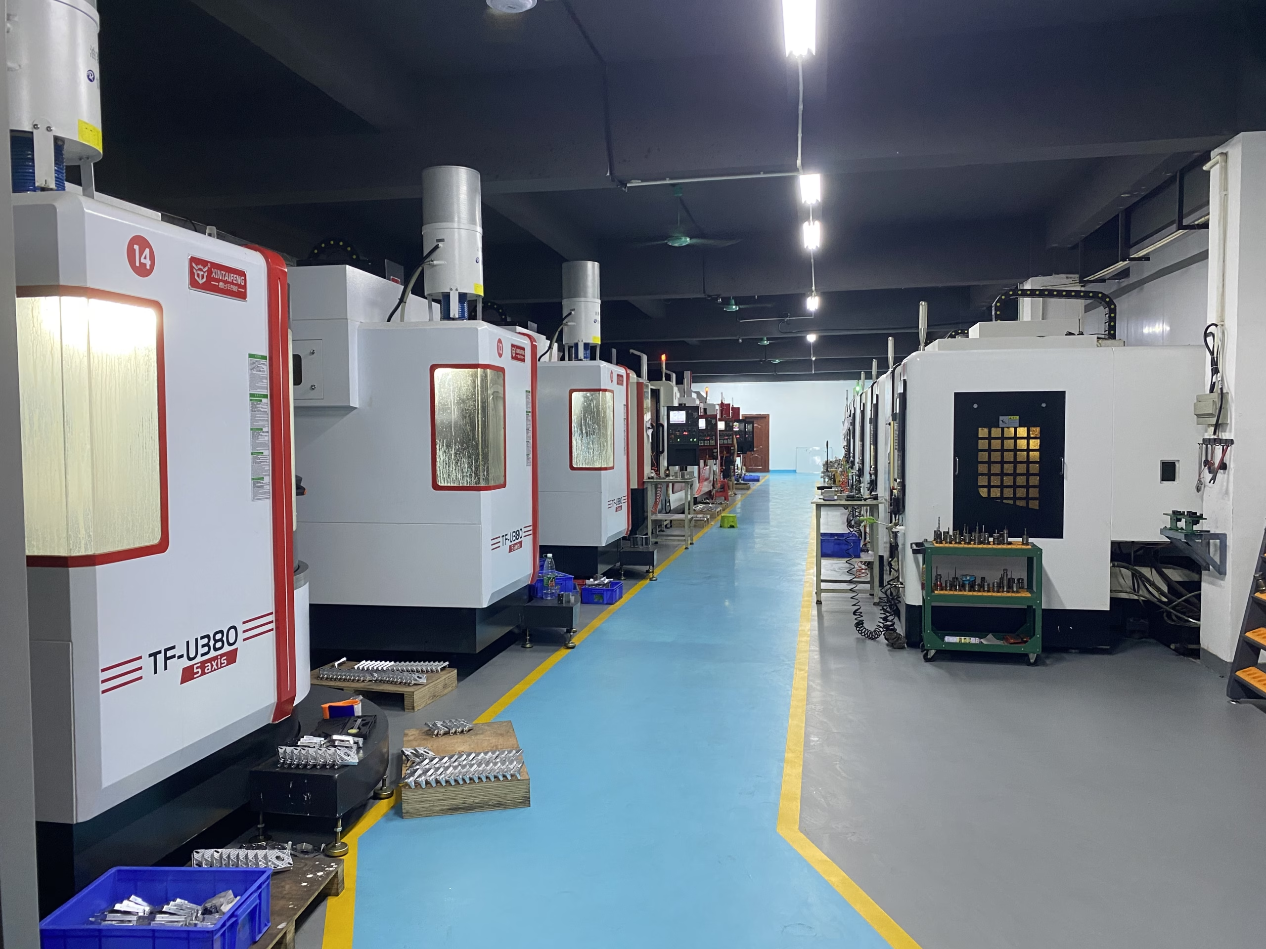
This is the moment to consider upgrading to a more professional-grade solution. For clients who need precision parts with complex geometries, high surface finishes, and tight tolerances, the jump from a 3-axis desktop router to a 5-axis machining center is the ultimate solution. A 5-axis system can machine a part from multiple angles in a single setup, eliminating the cumulative error of repositioning. This is where companies like GreatLight CNC Machining Factory truly excel. We are not simply a machine shop with a CNC 3040; we are your partner for precision parts manufacturing and integrated solutions.
Our facility is equipped with a full arsenal of technology—from high-precision 5-axis, 4-axis, and 3-axis machining centers to complementary processes like die casting, sheet metal work, and a full suite of 3D printing technologies (SLM, SLA, SLS). This allows us to offer solutions for your most demanding projects, whether they are complex engine components for the automotive industry, intricate medical hardware, or lightweight aerospace parts.
Choosing the right partner means selecting a company with real operational capabilities and a proven track record. We combine technical expertise with uncompromising standards. Our ISO 9001:2015 certification ensures product quality, while our adherence to ISO 13485 for medical hardware and IATF 16949 for automotive production guarantees that every part meets the highest industry-specific requirements. We don’t just cut metal; we engineer solutions that drive your innovation.
Conclusion: From Costly Mistakes to Precision Success
Mastering a CNC 3040 is a journey of understanding the fundamental principles of manufacturing. By internalizing these seven secrets—tramming the spindle, choosing the right work-holding, using a roughing/finishing strategy, respecting the machine’s stiffness, evacuating chips, understanding materials, and knowing when to scale up—you move from a tentative hobbyist to a confident maker. You will stop breaking tools, wasting material, and experiencing frustrating failures. Instead, you will begin creating precise, reliable parts that function as intended.
The knowledge you gain here is directly transferable to the world of professional manufacturing. When your project demands a level of precision, complexity, or speed that the 3040 simply cannot provide, remember that you have a trusted partner for custom precision parts. Reach out to a team that understands the science and art of manufacturing. Your next masterpiece deserves the right tool for the job.



















