
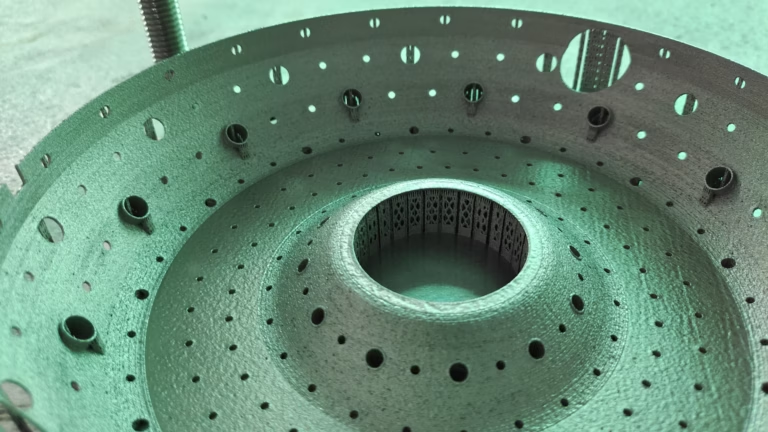
As a manufacturing engineer with over a decade at the intersection of digital design and physical production, I’ve seen countless parts fail not because of poor engineering, but because of a broken workflow between the screen and the machine. 3D Printing With Fusion 360: 7 Essential Tips to Master — whether you’re a moonlighting hardware hacker, a startup moving from prototype to pilot run, or a seasoned supplier evaluating additive capacity – is about more than just learning menus. It’s about understanding how to design for the physics of your chosen process, and knowing when that process should not be 3D printing at all.
We’ve been machining precision parts in Chang’an Town, Dongguan, since 2011. We’ve also installed and run SLM, SLA, and SLS printers for years. So we’re not speaking hypothetically. These seven tips come from real production floors, real inspection reports, and real conversations with customers like you who want reliable, honest manufacturing.
The Landscape: Why Fusion 360 Is Both Slicer and Scythe
Fusion 360 has quietly become the Swiss Army knife of the modern product development cycle. It’s not just a CAD tool. It integrates design, simulation, generative workflows, and even an additive manufacturing environment in a single subscription. For engineers, that’s a double-edged sword: you have more power than ever to create problems, and more power to solve them before they cost you money.
But here’s the dirty secret: Fusion 360 will happily let you design a part that looks perfect in a shading view and is completely unprintable. The software expects you to know a few ground rules. Below are the seven I consider non-negotiable.
3D Printing With Fusion 360: 7 Essential Tips to Master
1. Design for the Additive Process, Not the CAD Geometry
Most engineers learned to design for milling: sharp internal corners, thin walls, uniform thicknesses, and bosses that require machining tool access. That mental model can sabotage a 3D printed part.
In Fusion 360, you have a “3D Print” utility embedded in the Make menu. But that little dialog only exports a mesh – it doesn’t validate manufacturability. You need to apply Design for Additive Manufacturing (DfAM) rules manually:
Wall thickness: For FDM/FFF, a wall below 0.8–1.0 mm is likely to warp or delaminate. For SLM (metal powder fusion), thin walls below 0.3 mm become unsupported and may blow away. I usually model a minimum of 0.5 mm for metal and 1.2 mm for plastics, unless the feature is purely cosmetic.
Overhangs: Fusion 360 lets you angle any sketch or body. Self-supporting angles for most powder bed processes are 45 degrees or less from vertical. If you need a 90-degree lip, you either add a support lattice or you chew up time in post-processing.
Internal cavities: Without escape holes, powder or resin gets trapped. In Fusion 360, use the Hole command on any enclosed cavity and make sure there’s at least one 3–5 mm opening per cubic centimeter of volume.
Pro tip: Use the Inspect → Distance and Section Analysis tools in Fusion 360 to check wall thicknesses across a cross-section. It’s faster than guessing.
2. Navigate Between Solid and Mesh Workspaces with Intent
Fusion 360 supports two distinct worldviews: the parametric solid environment and the mesh workspace. Most beginners stay in one, and the design becomes a mess.
For mechanical brackets, enclosures, and mounts, use the solid workspace. It’s parametric, so you can tweak a dimension and have the whole assembly update. That’s critical when you’re iterating on clearances.
For organic, generative, or scanned geometries, use the Mesh workspace. But be careful: converting a mesh to a solid in Fusion 360 (using the “Mesh to B-rep” tool) can yield thousands of tiny faces that choke downstream operations. Instead, try Re-mesh with a target face count, then use Create Form (TSpline) to wrap a smooth cloud around the mesh.
Here’s a practical workflow I use daily:
Import the mesh.
Use Mesh → Modify → Reduce to simplify.
Convert to a TSpline body.
Convert TSpline to B-rep.
Then add mounting bosses and holes in the solid environment.
This gives you both freedom and manufacturability. Without that two-step, you’re likely to get a part that looks great but fails on a CMM.
3. Orient the Part for the Real Loading Condition, Not for Aesthetics
The single most impactful decision in the entire build process is the orientation of the part on the build plate. It affects:
Mechanical strength (layer adhesion is anisotropic – FDM parts are 40–60% weaker along the Z-axis; SLM parts are more isotropic but still have texture).
Surface finish (downward-facing faces are rougher, especially in powder bed processes).
Support material (every cubic centimeter of support you add is waste, but every unsupported overhang is a potential failure).
In Fusion 360, there isn’t a dedicated orientation recommendation engine in the base package (unlike Netfabb or Magics). But you can simulate it yourself.
Use the Move/Copy tool to rotate the part.
Then use the View → Display → Show All Edges to examine overhangs in wireframe.
Or switch to ViewCube and select the bottom face orientation.
The rule of thumb: place the most dimensionally critical features either vertical or at a 45-degree angle, never in a flat zone that faces down. Also, consider whether the part needs to be cut into two pieces and joined – sometimes that’s more robust than orientation gymnastics.
We had a client who designed a heat sink bracket with fine fins. They printed it standing up, and every fin warped because it acted like a thin cantilever. After a quick orientation change and adding a solid base that we later machined off, the fins remained straight. The lesson: don’t rely on print software “plating” to fix a poor orientation.
4. Treat Support Generation as a Design Task, Not a Slicer Default
In Fusion 360’s Additive workspace (the “Neutron” engine, now part of the software), you can generate supports directly. But the default supports are usually blocky and waste material. Worse, in metal printing, a dense support interface can bind to the part and require massive heavy machining to remove.
Instead, model your own supports when you can:
Use thin ribs or lattice structures that you generate in Fusion 360’s Design workspace. For example, a 0.5 mm vertical rib under a boss or flange. After printing, snip it off and set it through a quick belt sander.
Increase the overhang angle in the part design itself. In Fusion 360, you can use the Chamfer tool on a lip, turning a 60-degree overhang into a 45-degree one. This eliminates the need for support entirely.
For metal SLM, consider designing a “break-away” lattice with a few contact points rather than a solid contact. In Fusion 360, you can use the Insert → Pattern tool to create a grid of small pins that will snap off.
When you do rely on automatic supports, reduce their density to 5–10% in the slicer (if you’re exporting to an external slicer), or in the Additive workspace settings. You’ll save material and cut down post-processing time.
Remember: every support mark is a surface artifact. If the surface is functional or visible, it must be machined off. That’s why at GreatLight, we often recommend a hybrid approach – print the near-net shape, then finish the critical faces with our 5-axis CNC machining centers. That combination gives the best of both: design freedom and tolerance accuracy.
5. Set Clearances and Tolerances That Match the Process
The mechanical tolerance of a 3D printed part is dramatically different from milled parts. A typical FDM part holds ±0.5% of the dimension (roughly ±0.25 mm per 50 mm), while a well-tuned SLA printer can achieve ±0.1 mm, and metal SLM holds ±0.1–0.2 mm with proper calibration. Compare that to our in-house 5-axis CNC machining, which routinely hits ±0.001 mm (one micron) on critical features.
So when you design a shaft in a hole in Fusion 360, do not use a standard H7/g6 fit (that’s a precision class for machining). Instead:
For FDM, add 0.3–0.5 mm clearance on bore diameters for a sliding fit.
For SLA, 0.15–0.25 mm clearance.
For SLS, the powder does not absorb as much, so 0.2 mm is typical.
For SLM metal, add 0.3 mm for a slip fit, but leave 0.05 mm for a press fit if you plan to ream it afterward.
Fusion 360 has a Fit/Snap tool under Modify, but it assumes geometric perfection. Instead, use the Offset command on circular edges to generate intentional radial clearances. Another trick: use the Dimension in a sketch to reference a formula, e.g., D = dia and then set another dimension to D + 0.4. By using Model Parameters, you can quickly flip between manufacturing methods by changing a single value.
6. Use Simulation and Generative Tools to Earn the Right to Print
Printing carbon fiber reinforced nylon to save 2 grams of weight is pointless if a simple machined bracket is stronger and cheaper. But you can’t know that without simulation.
Fusion 360 includes a built-in Static Stress Simulation (valid for a single body). You can apply loads and fix constraints, then run a mesh convergence study. It’s not as powerful as a cloud FEA tool, but it’s enough for the first pass.
Here’s the workflow I recommend:
Assign the linear material properties of your chosen resin/powder.
Apply load cases – use factor of safety of 2 for prototypes, 3 for production parts.
Run the simulation.
If it fails, go back to orientation or thicken sections.
Then run Generative Design (you’ll need a higher-tier subscription). Fusion asks for loads, constraints, and manufacturing methods. You can specify “unrestricted” or “additive” to generate a lattice-like bone structure. This often reduces weight by 75% and stress concentrations by 40%.
But beware: purely generative geometry is almost always best made with 3D printing. If you intend to produce thousands of parts, you may want to take the generative result and remodel it with machining constraints in mind. That’s exactly what we do with many customers – we take their generative output, simplify it for 5-axis milling, and deliver a part with all the strength but at a fraction of the unit cost.
7. Know When 3D Printing Is Not the Answer: The Hybrid Strategy
This last tip is less about Fusion 360 and more about manufacturing common sense. In the industry, there’s a growing trend of “additive bragging rights” – everyone wants to print everything. That’s often wrong.
Volume: If your quantity exceeds 500 pieces and the part fits in a 100×100×100 mm box, extrusion or injection molding will crush the price of 3D printing.
Tolerance: For press-fit bearings, fine-threaded holes, or sliding fits, printed tolerances won’t suffice. You need a secondary machining operation on critical faces.
Surface finish: For optical or sealing surfaces, printing looks like a lunar landscape. A quick pass on a CNC vertical mill will make it flat within 0.01 mm.
Material properties: Injection-molded ABS or die-cast aluminum have better fatigue life and heat resistance than almost any printed equivalent.
So here’s my practical advice: design in Fusion 360 with both processes in mind. Use the Configuration capability (introduce model configurations) to switch between a print-ready version and a machined version. For example, maintain a version with 0.2 mm extra material on critical bores, and then if you decide to go the machined route, you remove that offset. This is a trivial task in Fusion 360 but saves days of rework.
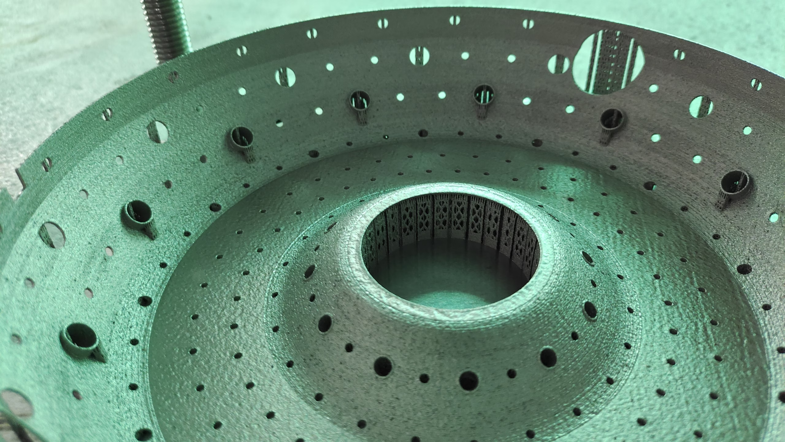
We practice this hybrid every week. A customer might bring a medical device part for a patient-specific surgical guide. The complex internal topology is printed in titanium via SLM, but the connection to the standard handle is machined after printing to achieve a secure slip-fit. Or a consumer drone component: the body is SLS-printed in PA12, but the threaded brass inserts are press-fit into CNC-machined pockets. That’s the real world of modern manufacturing.
Why Partner with a Manufacturer That Understands Both Toolboxes
In the past year, I’ve seen manufacturers that claim “we do everything” but outsource the additive steps and lose quality control. Others print every part without ever touching a lathe, and their customers suffer from poor dimensional accuracy. The best results come from a partner who has deep knowledge of both.
That’s the foundation of GreatLight Metal (GreatLight CNC Machining). We’re not a software company. We’re a factory floor operation. But the reason we keep Fusion 360 in our front office is that it lets us talk to you in your language – and then hand your model to the correct machine.
Additive equipment: We run SLM printers for stainless steel, aluminum, and titanium alloys, as well as SLA and SLS for plastics.
Subtractive equipment: Our 5-axis CNC machining centers from Dema and Beijing Jingdiao handle complex geometries up to 4000 mm. We’ve got 127 pieces of precision equipment in a 76,000 sq. ft. facility.
Certifications: ISO 9001:2015, IATF 16949 for automotive, ISO 13485 for medical devices. Those are not badges – they’re rules that govern our daily work.
When you design in Fusion 360 and export an STL, you’ve only done half the job. The other half is a conversation: How many parts? What loading? What finish? What tolerance band is real? We’ve had decades of experience with both 3D printing and precision CNC machining. We can tell you when a part should be printed, when it should be machined, and when it should be a print-then-machine hybrid. That saves you money, lead time, and heartbreak.
The Future Is Fluid, but the Principles Stay
Fusion 360 continues to evolve. New additive features appear, cloud simulation becomes cheaper, and generative design gets smarter. But the physics of fusion, sintering, and layer adhesion remain simpler to predict. Once you master the seven tips above, you can approach any print job with confidence:
Design for the process, not the screen.
Choose the right workspace.
Orient for function.
Support intelligently.
Tolerate realistically.
Simulate before build.
And never forget that subtraction has its place.
So whether you’re prototyping a robot gripper in your garage or commissioning a titanium implant for a clinical trial, remember those fundamentals. And when it comes to execution, find a partner who knows when to melt powder and when to spin a spindle.
As you work on your next design back in Fusion 360, ask yourself: am I printing this because it’s the smartest route, or because it’s easy? Then let’s talk if you’d like a second set of eyes. We’re here to make sure your part doesn’t just print – it performs.
3D Printing With Fusion 360: 7 Essential Tips to Master – those tips were developed not from a textbook, but from thousands of hours on the shop floor. Apply them, and you’ll find that your success rate climbs as fast as your waste bin empties. And if you’re ever in doubt about a material, a tolerance, or a geometry, reach out to us through our LinkedIn page. We’re always willing to share what we’ve learned.
[Internal link on “3D Printing With Fusion 360” to the precision 5-axis CNC service page]
[External link on last occurrence of “CNC machining” or “GreatLight” to LinkedIn]



















