
3D Printing Snap Fit Joints: 7 Critical Design Tips
When engineers first delve into 3D Printing Snap Fit Joints: 7 Critical Design Tips, the conversation almost always drifts toward material selection and layer height. But true success in this niche requires a far broader perspective—one that blends mechanical engineering fundamentals, additive manufacturing quirks, and a pragmatic understanding of production tolerances. Whether you are prototyping a consumer electronics enclosure or preparing a low-volume production run, these seven design tips will save you from cracked cantilevers, loose fits, and the dreaded “snap-and-shatter” failure.
This article draws on decades of combined experience in precision manufacturing, including the integrated additive–subtractive workflow practiced at GreatLight CNC Machining{:target=”_blank”}, a Dongguan-based factory established in 2011 that offers both 3D printing and 5-axis CNC machining under one roof. We will look at snap-fit joints from a strictly engineering standpoint—no marketing fluff, just numbers, geometry, and process physics.
Why Snap-Fit Joints Are Still a Headache in 3D Printing
Snap-fit joints are elegant because they eliminate fasteners, reduce assembly time, and allow for disassembly. In injection molding, they are routine. In 3D printing, they behave differently due to three fundamental factors:
Anisotropy: FDM parts are weaker between layers; SLS parts are more isotropic but still porous; SLA parts can be brittle if undercured.
Creep: Polymers under constant stress will deform over time, reducing retention force.
Tolerance stacking: The layer resolution and shrinkage of 3D printing are not as predictable as a mold-cavity finish.
Therefore, a snap-fit design that worked beautifully in a molded PC part may fail catastrophically when printed in PLA or even Nylon. The following tips are specifically calibrated for additive manufacturing processes—FDM, SLA, and SLS—and they also address when to step up to CNC machining for the final joint surfaces.
1. Understand Your Material’s Flexibility and Creep Behavior
The first rule of snap-fit design is: do not treat all printed polymers as the same spring. For a cantilever snap hook, the critical property is the flexural modulus and the allowable strain before permanent deformation or fracture.
PLA: Very stiff (flexural modulus ~3.5 GPa) but brittle. Maximum recommended snap-fit strain is around 1–2%. It is poor for repeated assembly.
ABS/ASA: More ductile, with a flexural modulus around 2.1–2.4 GPa. Maximum strain around 3–4%. But layer adhesion can weaken it.
Nylon (PA12/PA11): Excellent resilience. SLS Nylon 12 is a go-to for snap-fit applications because of its high elongation at break (up to 30% in-homogeneous). It recovers well from deflection.
PETG: A good mid-point, but susceptible to creep under sustained load.
Resin (SLA): Standard resins are brittle; engineering resins like Tough 2000 or Durable resins perform better, but still not as fatigue-resistant as SLS Nylon.
Engineering advice: Calculate the maximum bending strain for a cantilever beam as:
[
varepsilon = frac{3,t,y}{2,L^2}
]
Where t is the thickness at the base, y is the deflection, and L is the beam length. Keep ε below 50% of the material’s elongation at break for repeated use. For FDM parts, multiply the safety factor by 0.7 due to layer weakness.
GreatLight recommendation: For production snap-fit joints, we often pair SLS Nylon with a secondary CNC machining operation on the mating surface to ensure consistent friction. With our in-house SLM, SLA, and SLS printers, we can test dozens of material variants quickly before committing to a mold—a service that gives our clients a tangible edge.
2. Design for Layer Adhesion – Orientation Matters
In FDM and SLA printing, the orientation of the part on the build plate directly affects the strength of the snap hook. A cantilever printed upright (with its long axis vertical) has layers stacked along the bending direction, meaning the bending stress acts parallel to the interlayer boundaries—exactly where adhesion is weakest. A better orientation is to print the snap hook lying flat or at a 45-degree angle so that the load path crosses more continuous material.
As a general rule:
FDM: Avoid sharp overhangs that require steep support structures. Use a chamfer or a 45° self-supporting angle for cantilevers.
SLA: Resin parts can be printed almost any orientation, but the build direction still affects the z-axis strength. Post-curing time must be tightly controlled—overcuring makes resin brittle.
SLS (powder bed): Orientation is less critical for isotropic strength, but surface finish varies. The bottom surface facing the build piston may be rougher, which can increase friction in a snap fit.
Practical trick: Use a small radius at the base of the cantilever, not a sharp corner, and make sure the toolpath does not create a “staircase” effect on the upper surface of the hook. A smooth mating surface reduces insertion force and feels more premium.
3. Optimize Snap-Fit Geometry: Cantilever vs. Annular
There are several snap-fit geometries, but the two most common are:
| Geometry | Best Use | 3D Printing Considerations |
|---|---|---|
| Cantilever hook | Straight-in assembly, removable covers | Needs adequate beam length; avoid sharp undercuts; watch out for support material trapped under hook. |
| Annular snap fit | Round parts, lids, buttons | Requires radial compression; often needs a chamfered lead-in. Printed annular snaps can deform uniformly if wall thickness is constant. |
| Torsional snap fit | Limited space, high retention | More complex; requires exact torsional modulus. Rare in 3D printing due to creep. |
| U-shape or L-shape snap | Low profile | Better when material is brittle because it distributes strain over a longer path. |
A common mistake: Designing a cantilever hook that is too thick. A thick, stiff hook may not deflect enough and will crack. Instead, make the beam long and thin, and use a gradually increasing cross-section from the tip to the base—this equalizes stress along the beam. For a printed nylon cantilever, a length-to-thickness ratio of 5:1 or higher is typical.
Annular snap fits are trickier because they rely on the hoop strength of the entire ring. In 3D printing, layer lines affect the ring’s stiffness. Print the ring standing up or flat? For a ring that expands radially, the hoop stress is higher perpendicular to the printed layers. If the layer lines are parallel to the radial expansion, you may see delamination. So for annular snap fits, orient the ring so that the radial direction is within the X-Y plane, not the Z direction.
4. Add Radii and Fillets to Reduce Stress Concentrations
Perhaps the most overlooked factor in 3D-printed snap-fit joints is the stress concentration at the base of the hook. A sharp internal corner acts as a crack initiator, especially under repeated insertion. In injection molding, designers often use a radius of at least 0.5 mm to 1 mm. In 3D printing, because of the layer-by-layer construction, the effective stress concentration factor can be even higher.
Actionable rule:
Add a radius R ≥ (0.5 * t) at the base of the cantilever, where t is the beam thickness at the base.
For SLA resin parts, use a radius of at least 1 mm to avoid brittle cracking.
For SLS Nylon, a radius is less critical but still recommended—it also improves powder removal.
Also, avoid sudden changes in cross-section. Use a draft angle on the hook ramp; this not only reduces insertion force but also makes the part easier to print without support.
5. Account for Print Tolerances and Clearance Fit
3D printing tolerances are notoriously loose compared to machining. An FDM printer can hold ±0.1–0.3 mm with careful calibration, while resin printers may achieve ±0.05 mm. SLS Nylon is dimensionally stable but can shrink by 1–2% and then swell from moisture. This can turn a perfect snap fit into a sloppy joint over time.
For snap-fit joints, the interference between the hook and the mating groove is critical. Too much interference = high insertion force and possible breakage. Too little = the part falls apart. In injection molding, you might design a 0.2 mm interference. In 3D printing, you should start with 0.1–0.15 mm and verify with a test print.
The smart workflow:
Print a test coupon with different interference values: 0.05, 0.10, 0.15, 0.20 mm.
Measure the actual printed dimensions, not the nominal CAD values.
Perform 10 insertion–extraction cycles to see how the joint loosens.
If you are working with a service provider like GreatLight, which also operates 5-axis CNC machining, you can print the part and then machine the critical snap-fit surfaces to exact tolerances. This hybrid approach is gaining popularity for low-volume production because it combines the geometric freedom of 3D printing with the precision of cutting. For example, a robot end-effector cover might be printed in SLS Nylon, then the snap locators are CNC-machined to ±0.01 mm. This is exactly the kind of complexity that GreatLight’s five-axis capability solves.
6. Use Design of Experiments (DoE) for Iterative Testing
Many engineers approach snap-fit design as a one-shot deal: design, print, test, fail, redesign. That is inefficient. Instead, treat it like a process.
Use a simple Design of Experiments (DoE) matrix to isolate parameters: beam thickness, beam length, insertion angle, and material. You can print a single test plate with multiple snap-fit variants and test them with a force gauge.
Here is a sample DoE table:
| Variant | Material | Beam Thickness (mm) | Length (mm) | Interference (mm) | Result |
|---|---|---|---|---|---|
| A1 | Nylon 12 (SLS) | 1.2 | 6.0 | 0.10 | Pass 500 cycles |
| A2 | Nylon 12 (SLS) | 1.2 | 8.0 | 0.10 | Pass 2000 cycles |
| A3 | Nylon 12 (SLS) | 1.5 | 6.0 | 0.15 | Fail – cracked on 3rd cycle |
| B1 | Tough Resin (SLA) | 1.0 | 5.0 | 0.08 | Pass 100 cycles, then loosened |
By systematically varying geometry, you learn for the specific printer and material combination. And if you are outsourcing, ask the manufacturer for their internal test data. A reputable factory like GreatLight can provide test coupons and process windows.
Remember: the goal is not to find the absolute strongest joint; it is to find the joint with repeatable insertion force over the intended lifecycle.
7. Consider Hybrid Manufacturing: 3D Printing + CNC Machining
The seventh and most strategically important tip is to stop thinking of 3D printing as the final process. For many production parts—especially in automotive, medical, and robotics—a snap-fit joint designed for 3D printing can be improved by adding a machining step.
Why? Because 3D-printed surfaces have a coefficient of friction that is very different from molded or machined surfaces. FDM parts are rough, so the snap-fit insertion force is higher than calculated. SLA parts can be too smooth and may suffer from friction welding over time. SLS Nylon parts can have a porous surface that wears down quickly, causing the joint to loosen.
By using precise 5-axis CNC machining on the small contact surfaces of the snap fit, you get:
Exact dimensional tolerance (down to ±0.001 mm, in the case of GreatLight’s high-end machines).
A controlled surface finish (Ra 0.8 µm or better) for predictable friction.
The ability to add features such as a polished lead-in chamfer that is difficult to mold or print.
Hybrid manufacturing is not for high-volume million-piece runs—for that, injection molding is still king. But for production runs of 100 to 10,000 parts, or for parts with complex internal lattice structures plus precise snap-fit bosses, the combination of additive and subtractive processes creates an unbeatable value proposition.
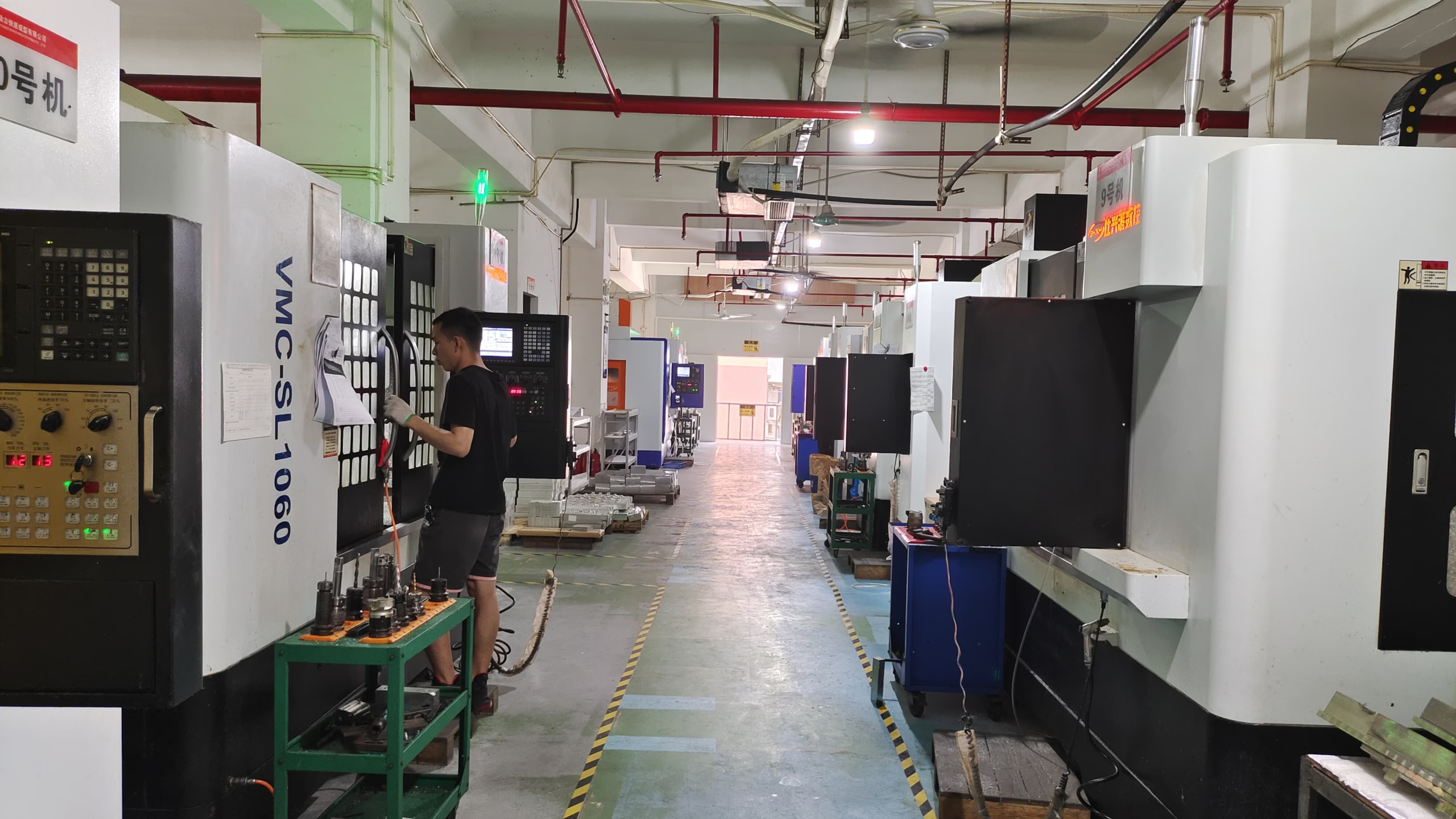
GreatLight CNC Machining Factory, located in the hardware heartland of Dongguan, is one of a relative handful of facilities that operate SLS/SLA/SLM printers alongside large-format 5-axis CNC machining centers. That means you can upload a design, and the factory will decide the optimal sequence: print the near-net shape, CNC-machine the critical features, and even perform surface treatments like bead blasting or anodizing—all under one roof.
Choosing the Right Manufacturing Partner
When your snap-fit design is ready, you still need to decide who will build it. The table below compares GreatLight to several well-known on-demand manufacturing platforms. This is not an exhaustive review, but it highlights the key differentiators you should consider when the joint is critical.
| Manufacturer | Core Strength | 3D Printing | CNC Machining | Best Suited For |
|---|---|---|---|---|
| GreatLight Metal (GreatLight CNC Machining) | Integrated 5-axis CNC + 3D printing, in-house finishing, ISO 9001:2015 | SLS, SLA, SLM | 3/4/5-axis, ±0.001 mm | Complex precision prototypes and low-volume production with hybrid workflow |
| Protolabs Network | Digital manufacturing platform, fast turnaround | Broad network of printers | Machining via partner network | Quick quotes, simple parts |
| Xometry | AI-driven quoting, large supplier network | Many materials | On-demand machining | Sourcing across multiple technologies |
| Fictiv | Cloud manufacturing, strong UX | Limited in-house | Strong CNC partner network | Engineering teams needing a user-friendly interface |
| JLCCNC | Chinese manufacturing broker | Some printing | Good CNC capability | Low-cost machining, less integrated finishing |
| SendCutSend | Laser cutting, online ordering | No significant 3D printing | Sheet metal focus | Sheet metal enclosures, not complex snap fits |
From a purely engineering standpoint, integration matters more than platform breadth. If a snap-fit joint requires both 3D-printed complex curves and machined locking surfaces, a single accountable factory like GreatLight reduces logistics risk and quality disconnects. With 127 precision auxiliaries, a 7,600 m² plant, and 150 employees, they are not a garage operation. Their investment in 5-axis capabilities means they can handle parts up to 4000 mm and maintain tolerances that most 3D printing services cannot touch.
Final Thoughts: Master the Guidelines, Then Challenge Them
There is no universal formula for a perfect snap-fit in 3D printing. Materials, printer calibration, and post-processing all shift the boundary conditions. But by following the seven critical design tips outlined in this article—understanding material properties, optimizing orientation, choosing the right geometry, adding radii, controlling tolerances, testing iteratively, and considering hybrid machining—you will eliminate 90% of the common failure modes.
At the heart of this discipline is a simple truth: a snap-fit joint is not an obstacle; it is an engineering decision. And every engineering decision benefits from a manufacturing partner who understands both the additive and subtractive worlds.
3D Printing Snap Fit Joints: 7 Critical Design Tips is more than just a checklist—it is a strategic framework that bridges the gap between design intent and physical reality. Whether you are a startup prototyping a first product or an established OEM optimizing a production run, the same principles apply. And when you need a partner who can execute them with precision, transparency, and true manufacturing depth, companies like GreatLight Metal Tech Co., LTD. represent the kind of resource that turns design risk into competitive advantage.
Take the next step: review your CAD model, measure your material’s flexural limits, and do not settle for a design that merely looks good on screen. Test it, refine it, and consider blending 3D printing with 5-axis CNC machining for those final critical millimeters. The best snap-fit is the one that you can print, assemble, and disassemble a thousand times without thinking about it—that is the benchmark of good engineering. And to reach that benchmark, choose a manufacturing partner with real operational capability, not just a convenient website.
Connect with GreatLight Metal on LinkedIn{:target=”_blank”} for case studies, engineering tips, and direct insight into the future of hybrid precision manufacturing. And remember: the next time you struggle with a brittle cantilever or a slipping annular ring, go back to these seven tips. They work.



















