

As a senior manufacturing engineer at GreatLight CNC Machining Factory, I’ve seen firsthand how the 10 CNC Milling Machine Working Secrets Every Engineer Should Know can separate mediocre results from world-class precision.
10 CNC Milling Machine Working Secrets Every Engineer Should Know
Whether you’re designing a next-generation robot joint, a medical implant, or an automotive powertrain component, CNC milling often stands between your CAD model and a functional part. Yet most engineers only scratch the surface of what modern milling can do. Over the last decade, our team at GreatLight has turned complex metal parts into exacting production reality using advanced 5-axis CNC machining, and along the way we’ve accumulated insights that go far beyond machine manuals. Here are ten genuine “secrets”—practical, physics-based methods—that separate capable shops from those delivering micron-level consistency.
Secret #1: Dynamic Workholding Is the Hidden Backbone of Accuracy
A milling machine can be precise to ±0.001 mm in its positioning, but if the workpiece moves just a few microns during cutting, that precision evaporates. Dynamic workholding means designing the fixture to match both the part geometry and the cutting forces, not just clamping it as tightly as possible. For example, when we machine thin-walled aerospace brackets, we don’t rely solely on vise jaws; we use bespoke soft jaws contoured to the part, supported by vacuum assist or low-melt-point alloys that dampen vibration and distribute clamping forces. GreatLight’s zero-point pallet systems allow us to swap fixtures between 3-axis, 4-axis, and 5-axis machines without losing positional reference—a key reason our multi-setup jobs maintain ±0.005 mm across batches.
The secret: identify the direction of the dominant cutting force vector, and apply holding forces exactly opposite that vector, using modular fixturing that minimizes overhang. This alone can improve roundness and flatness by more than 40% on delicate parts.
Secret #2: Trochoidal Milling Unlocks High-Efficiency Roughing
Conventional slot milling buries a large portion of the tool edge in the work, generating excessive heat and tool deflection. Trochoidal milling uses a circular tool path with a small step-over (typically 5–15% of tool diameter) and high feed rates, maintaining a constant chip load. The result: radial cutting forces drop dramatically, tool life often triples, and you can use the full depth of the tool length without chatter. On titanium alloy frames for humanoid robots, we run 12 mm end mills at full 5×D depth with a 0.6 mm step-over, achieving material removal rates that match bulkier roughing strategies but with far less tool wear.
The secret lies in CAM software that calculates adaptive constant-engagement paths. GreatLight’s programmers leverage advanced toolpath algorithms that dynamically adjust feed to maintain spindle load, avoiding overload pockets. This isn’t just roughing—it’s intelligent roughing that leaves a uniform stock for semi-finishing, a crucial step many shops skip.
Secret #3: Thermal Compensation Strategies Eliminate the Midnight Drift
Machine tool structures expand and contract with temperature. A 1°C change in a 500 mm column can cause over 5 µm of positional drift (more on aluminum ball screws). Many job shops accept that morning-after-pause parts will differ from afternoon-parts. We don’t. Our manufacturing floor maintains a 20±1°C climate, but we also deploy in-machine probing at defined intervals. Before any tight-tolerance finish pass, the probe measures reference features on the part or fixture; the CNC then auto-compensates offsets based on thermal error mapping. On our 5-axis machines, volumetric compensation in the controller corrects for linear, angular, and twist errors in real time.
The secret is understanding that thermal growth isn’t linear. Warm-up cycles matter: running a spindle at mid-RPM for 20 minutes while coolant circulates stabilizes the spindle’s internal thermal equilibrium, reducing Z-axis drift to less than 2 µm. GreatLight’s ISO 9001 procedures include rigorous warm-up and probing protocols, ensuring that a part machined at 8 AM matches one machined at 11 PM.
Secret #4: Toolholder Runout—Microscopic Error, Macroscopic Consequence
Runout—the eccentricity between the tool’s axis and the spindle’s axis—compounds dramatically. At 3 µm runout, a multi-flute end mill will see one flute doing most of the cutting, causing uneven wear, poor surface finish, and premature failure. We exclusively use HSK-A63 interfaces on our high-speed machines, because the dual-contact face and taper grip provide repeatability under 2 µm. Combined with shrink-fit holders and precision collets with T.I.R. (total indicated runout) below 3 µm, we ensure every cutting edge shares the load evenly.
For engineers designing parts, this secret means you can specify finer surface finishes and tighter tolerances (like 0.8 Ra on a pocket floor) only if you know the production shop controls runout. At GreatLight, we verify runout with a laser tool setting system on every tool change, capturing dynamic runout at operating RPM, not just static. This practice has eliminated a recurring issue of “mystery” chatter on medical device components.
Secret #5: Adaptive Programming and CAM Automation Aren’t Just Buzzwords
True adaptive machining goes beyond feed-rate ramping. It involves using on-machine probing data to adjust toolpaths in mid-program. For instance, when casting or 3D-printed blanks vary by ±0.3 mm from the nominal model, a traditional CAM path would either air-cut or over-engage. Our process: the probe maps the actual stock envelope, the CAM reconstructs a mesh, and the toolpath recalculates to maintain consistent chip load from part to part. This is how we machine near-net-shape investment castings for valve bodies without sacrificing efficiency or risking tool shock.
The secret is integrating probing macros with parametric CAM—a capability we’ve refined at GreatLight by combining custom post-processors with powerful CAM software. Engineers who design with stock allowance variations in mind enable this automation, reducing cycle time by 15–20% while protecting expensive tools.
Secret #6: Thin-Wall Machining Requires a Surgeon’s Touch, Not a Hammer
When milling walls below 0.5 mm thickness, the structure becomes a tuning fork. Any aggressive radial cut induces vibration that leaves a washboard surface and dimensional distortion. The remedy: “waterline” strategies with reduced axial depth of cut (0.02–0.05 mm) and high spindle speeds, combined with asymmetric relief passes. We also use rest machining with progressively smaller tools to remove only the inner skin, leaving the surrounding material for support until the very end. For electronic housing prototypes, we’ve produced 0.3 mm walls in aluminum 6061 with flatness within 0.01 mm using this approach.
The hidden secret: harmonic avoidance. By intentionally varying spindle speed increments (say, 12,000 RPM for one pass, 12,200 RPM for the next), we break up resonant frequency bands that cause chatter. Our machinists use audio feedback and accelerometer data to fine-tune these parameters, a practice born from decades of tackling difficult cantilevered features.
Secret #7: Minimum Quantity Lubrication (MQL) Can Redefine Surface Integrity
For aluminum and certain steels, flooding coolant isn’t always best. MQL—a fine aerosol of oil droplets—lubricates the cutting edge directly while the dry cutting zone evacuates chips via powerful air blast. The result is lower thermal shock to the tool (no constant quenching) and cleaner parts that need minimal degreasing. On 7075-T6 aircraft parts, we’ve seen surface roughness improve from 1.2 Ra to 0.6 Ra after switching to MQL with a dedicated high-pressure nozzle, along with a 30% increase in tool life.
The secret is that MQL demands precise nozzle alignment and oil mist volume calibration. Too little lube and you build up edge; too much and you stain the part. GreatLight’s process engineering team develops MQL recipes per material alloy and tool coating (TiAlN vs. DLC) through iterative cutting trials—data we share with clients to justify design choices that accommodate near-dry machining.
Secret #8: Climb Milling vs. Conventional Milling—The Finish Line Is in the Chip
Most CNC programmers default to climb milling (tool feed in the same direction as cutter rotation) because it produces better finishes and lower cutting forces on rigid setups. However, conventional milling (cut against rotation) has its place: when machining hardened scales from forgings or when surface work-hardening must be avoided on stainless steel’s outer layer. The secret is to deliberately sequence operations: rough with conventional milling to peel away the crust without dragging it over the tool, then finish with climb milling for the final dimension. On a 316L surgical robot arm, we used this hybrid strategy to keep tool wear predictable and maintain a burr-free edge that eliminated manual deburring.
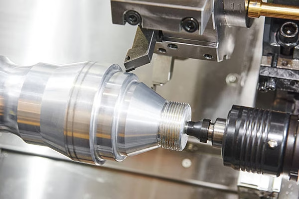
Understanding the chip thickness variation in each mode—thin-to-thick for climb, thick-to-thin for conventional—allows engineers to predict residual stress profiles. This insight is crucial for parts that undergo anodizing or electro-polishing later.
Secret #9: Tool Assembly Stiffness: The L/D Ratio That Silently Dictates Precision
When a tool’s length-to-diameter ratio exceeds 4:1, static deflection under radial load becomes the dominant error. A 10 mm end mill at 8×D stickout can deflect over 50 µm under moderate cutting forces, producing tapered walls and oversized bores. The solution isn’t always reducing stickout—sometimes it’s using anti-vibration bars with internal dampers, or carbide-reinforced shanks. On deep cavity molds for die casting, we employ modular tool extensions with HSK interfaces and shrinking technology to achieve near-solid stiffness even at L/D 7:1.
The secret is also in toolpath compensation: our CAM can predict deflection and scallop the toolpath to compensate, using virtual tool assembly modeling. This predictive approach enables us to hold H7 tolerances on bores 150 mm deep, a feat impossible without addressing stiffness head-on.
Secret #10: Rest Machining and 5-Axis Positioning Turn Complexity into Precision
Rest machining—using a smaller tool to clean only the areas the previous tool couldn’t reach—is standard practice. The real secret is coupling rest machining with full 5-axis positioning rather than just 3+2 indexing. By tilting the tool to access undercut regions or to present a shorter stickout, we eliminate the need for custom form tools and reduce setups. For an impeller with tight internal fillets, our 5-axis strategy allowed a 4 mm ball end mill to reach every blade surface in one continuous path, slashing cycle time by 40% and ensuring blending errors below 5 µm.
This capability is not just about the machine; it demands post-processors that accurately simulate machine kinematics to avoid singularities and tool holder collisions. GreatLight’s team has developed in-house simulation protocols using machine digital twins, ensuring that the complex paths generated by CAM are physically executable without any last-minute surprises on the shop floor.
When you put these secrets together, the result is a manufacturing environment where precision isn’t an accident. Our ISO 9001 quality system, climate-controlled facility, and comprehensive investment in metrology (from CMMs to laser interferometers) all reinforce these principles. We regularly partner with engineers from prototyping through to full-scale production, and we’ve seen that when designers understand these milling truths, their parts become inherently more manufacturable—and they can hold us to a higher standard with confidence.
In summary, embracing the 10 CNC Milling Machine Working Secrets Every Engineer Should Know provides a solid foundation for designing better parts, optimizing processes, and choosing a qualified manufacturing partner like GreatLight CNC Machining.



















