
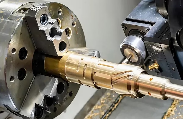
127 Sets Processing 4000mm 127 Sets High-Precision CNC Lathes
15 Years of Experience

7 Essential G17 CNC Programming Tips to Avoid Costly Errors

When it comes to CNC machining, the G17 command is one of the most fundamental yet frequently misunderstood codes. G17 selects the XY plane for circular interpolation, cutter compensation, and coordinate rotations—essentially telling the machine to operate in the horizontal plane. While it seems straightforward, misusing or overlooking G17 can lead to scrapped parts, broken […]

When it comes to CNC machining, the G17 command is one of the most fundamental yet frequently misunderstood codes. G17 selects the XY plane for circular interpolation, cutter compensation, and coordinate rotations—essentially telling the machine to operate in the horizontal plane. While it seems straightforward, misusing or overlooking G17 can lead to scrapped parts, broken tools, or even machine crashes. For precision parts manufacturers like GreatLight CNC Machining, mastering these nuances is part of the daily workflow. Drawing from over a decade of hands-on experience in high-precision five-axis machining, here are seven essential G17 programming tips that will help you avoid costly mistakes and improve your machining reliability.


1. Always Confirm the Default Plane at Program Start

Many CAM systems automatically output G17 at the beginning of a program, but not all controllers retain this setting after a reset or tool change. A common error is assuming the machine is still in G17 after a manual intervention or after running a subroutine that changed the plane (e.g., G18 for XZ or G19 for YZ).

Tip: Explicitly include G17 in your safety block—usually right after the G90 absolute positioning and G21/G20 unit selection. Even if your CAM adds it, placing G17 again before any circular interpolation or cutter compensation ensures the controller is in the correct plane. This simple habit prevents expensive crashes when operators manually override or restart a program mid-cycle.

At GreatLight, our ISO 9001:2015 certified process requires all programs to include a “safety header” with G17, G40 (cutter comp cancel), and G80 (canned cycle cancel). This standard eliminates variability across different machines and operators.

2. Understand G17’s Role in Cutter Radius Compensation (G41/G42)

Cutter radius compensation (CRC) relies heavily on the active plane. When G17 is selected, the compensation vector is applied in the XY plane—moving the tool left (G41) or right (G42) relative to the programmed path. A frequent mistake is using G41/G42 while the controller is in G18 or G19, which will apply compensation in the wrong axis set, leading to undercut or gouged features.

Tip: Always verify that G17 is active before and after any G41/G42 block. If you need to change planes within a single program (for example, milling on the side of a part with a right-angle head), cancel compensation with G40 first, switch to G18 or G19, then re-enter compensation.

For complex five-axis work, GreatLight’s engineers often use macro variables to store the current plane and automatically restore G17 after multi-axis moves—reducing human error and ensuring predictability.

3. Avoid Forgetting G17 When Using Circular Interpolation (G02/G03)

The IJ or R values for arcs are interpreted relative to the active plane. In G17, I is the X-axis offset, J is the Y-axis offset. If you forget to include G17 and the machine is still in G18 (XZ plane), the arc will be incorrectly calculated—potentially cutting into the part or creating a large spiral instead of a clean circle.

Tip: Make it a rule to write G17 immediately before every G02/G03 line, especially in manual programming or post-edited code. Even if your CAM already outputs it, adding it again does no harm and acts as a visual cue during code review.

GreatLight’s programming team enforces a “plane-first” discipline: every arc block is preceded by a comment line noting the intended plane. This practice has saved countless hours of rework, especially on large die-cast molds where errors are extremely costly.

4. Combine G17 with G90/G91 for Consistent Coordinate Rotations

Coordinate rotation (G68) rotates the coordinate system around a specified center point. The rotation occurs in the active plane—in G17, it rotates in XY. A common mistake is to activate G68 in G17, then switch to G18 for a different operation, and forget to cancel the rotation with G69. The machine will then rotate subsequent moves incorrectly.

Tip: Always cancel G68 (with G69) before changing planes, or explicitly reset the plane and rotation in the correct order. At GreatLight, we use a structured sequence: G69 → G17 → G68 X Y R_ … then after rotation work, G69 → G17 again. This sequence ensures no hidden rotations carry over.

For high-volume production, we also embed plane-checking logic in our post-processors, automatically inserting G17 and G69 at logical breakpoints.

5. Don’t Assume G17 is Active After a Tool Change

Tool changes can reset some controller parameters to default, including the active plane. Many older machines (and even some newer ones) revert to G17 after an M06, but not all. Additionally, if your machine has a “home” or “reference” routine that changes the plane, you may lose the XY selection.
图片

Tip: After every tool change, re-assert G17 before any movement. This is especially critical if you use a tool that requires a different orientation (like a face mill that cuts on the bottom). GreatLight’s standard practice includes a “tool change reset” macro that always sets G17, absolute mode, and feed rate override to 100% before continuing.

In our facility, we run over 127 precision machines daily. This single rule—re-asserting G17 after each tool change—has eliminated hundreds of potential crashes annually.

6. Use G17 Correctly with Hole-Making Cycles (G81, G83, etc.)

Canned cycles for drilling, tapping, and boring are also plane-dependent. While most cycles drill along the Z-axis (perpendicular to the XY plane), some controllers allow you to define cycle axes differently. If you accidentally leave the controller in G18, the drill cycle may attempt to move in the X or Y direction for the “Z” depth, resulting in broken drills or damaged parts.

Tip: Always precede any canned cycle with G17 (unless you specifically need a different plane for angular holes). For standard vertical machining centers, this is the safest approach. For five-axis or multi-angle work, use the correct plane and test the cycle in a safe height first.
图片

GreatLight’s engineers often simulate canned cycles in the machine’s dry-run mode before production. We also add G80 before each plane change to cancel any active cycle, then re-issue G17 and the new cycle.

7. Plan for G17 in Post-Processor and Simulator Settings

Many costly errors originate not from the G-code itself, but from how it’s generated or simulated. If your CAM post-processor doesn’t explicitly output G17 at the start of each toolpath group, or if your simulator assumes a different default plane, you might get the wrong toolpath despite correct manual programming.

Tip: Configure your CAM post-processor to output G17 at the beginning of the program and after every tool change. Also, verify that your simulation software uses the same plane logic as the actual controller. For critical parts—like those in aerospace or medical devices—GreatLight performs a back-plot comparison between the CAM simulation and the actual machine code.

We use proprietary scripts that compare the toolpath vectors to ensure every arc and compensation move aligns with the XY plane. This extra step has been instrumental in maintaining our consistent ±0.001mm tolerance across complex geometries.


Final Thoughts: The 7 Essential G17 CNC Programming Tips to Avoid Costly Errors

Mastering G17 is not just about writing correct code—it’s about building a reliable programming discipline that prevents errors before they happen. From double-checking default planes to integrating plane checks in macros and post-processors, every tip listed here comes from years of real-world problem solving at GreatLight CNC Machining. We’ve seen first-hand how a missing G17 can turn a $20,000 prototype into scrap metal. Conversely, systematic adherence to these practices enables us to consistently deliver complex parts with submicron precision and tight deadlines.

Whether you are programming manually or using advanced CAM, internalizing these seven tips will reduce rework, protect your machines, and save significant time and money. If you’d like to see how these principles are applied in full-scale production—especially in five-axis multi-material work—reach out to our engineering team through the 7 Essential G17 CNC Programming Tips to Avoid Costly Errors that we implement daily at GreatLight. We invite you to explore how a disciplined, ISO-certified approach to G-code management can elevate your own manufacturing results.

For more insights and professional discussions on precision machining standards, follow GreatLight Metal’s industry updates on LinkedIn.


CNC Experts

Picture of JinShui Chen

JinShui Chen

Rapid Prototyping & Rapid Manufacturing Expert

Specialize in CNC machining, 3D printing, urethane casting, rapid tooling, injection molding, metal casting, sheet metal and extrusion

CNC Recent Posts

CNC News

Welcome to GreatLight Metal,Maximum Processing Size 4,000 mm

Precision Machining CNC Quote Online

Loading file

Upload Click here to upload or drag and drop your model to the canvas.

The model is too large and has been resized to fit in the printer's build tray. [Hide]

The model is too large to fit in the printer's build tray. [Hide]

The model is too large, a fitting printer is selected. [Hide]

The model is too small and has been upscaled. [Hide]

Warning: The selected printer can not print in full color [Hide]

Warning: obj models with multiple meshes are not yet supported [Hide]

Warning: Unsupported DXF entity  [Hide]

Warning: could not arrange models [Hide]

[Hide]


File Unit:      
Scale:
%
L × W × H:
X: × Y: × Z:  cm 
Rotation:
X: ° Y: °  
⚡ Instant Quote for Precision Manufacturing

Submit your design files (STEP/IGES/DWG) and receive a competitive quote within 1 hour, backed by ISO 9001-certified quality assurance.

📋 How It Works

  1. Upload & SpecifyShare your 3D model and select materials (Aluminum/Stainless Steel/Titanium/PEEK), tolerances (±0.002mm), and surface treatments.

  2. AI-Powered AnalysisOur system calculates optimal machining strategy and cost based on 10+ years of automotive/aerospace data.

  3. Review & ConfirmGet a detailed breakdown including:
    - Volume pricing tiers (1-10,000+ units)
    - Lead time (3-7 days standard)
    - DFM feedback for cost optimization

Unit Price: 

Loading price
5 Axis CNC Machining Equipment
4 Axis CNC Machining Equipment
3 Axis CNC Machining Equipment
CNC Milling & Turning Equipment
Prototype and Short-Run Injection Moldings Exact plastic material as final design
Volume Metal Die Casting Services - Precision Cast Parts
Bridge the Gap From Prototype to Production – Global delivery in 10 days or less
Custom high-precision sheet metal prototypes and parts, as fast as 5 days.
Custom Online 3D Printing Services
Design Best Processing Method According To 3D Drawings
Alloys Aluminum 6061, 6061-T6 Aluminum 2024 Aluminum 5052 Aluminum 5083 Aluminum 6063 Aluminum 6082 Aluminum 7075, 7075-T6 Aluminum ADC12 (A380)
Alloys Brass C27400 Brass C28000 Brass C36000
Alloys Stainless Steel SUS201 Stainless Steel SUS303 Stainless Steel SUS 304 Stainless Steel SUS316 Stainless Steel SUS316L Stainless Steel SUS420 Stainless Steel SUS430 Stainless Steel SUS431 Stainless Steel SUS440C Stainless Steel SUS630/17-4PH Stainless Steel AISI 304
Inconel718
Carbon Fiber
Tool Steel
Mold Steel
Alloys Titanium Alloy TA1 Titanium Alloy TA2 Titanium Alloy TC4/Ti-6Al 4V
Alloys Steel 1018, 1020, 1025, 1045, 1215, 4130, 4140, 4340, 5140, A36 Die steel Alloy steel Chisel tool steel Spring steel High speed steel Cold rolled steel Bearing steel SPCC
Alloys Copper C101(T2) Copper C103(T1) Copper C103(TU2) Copper C110(TU0) Beryllium Copper
Alloys Magnesium Alloy AZ31B Magnesium Alloy AZ91D
Low Carbon Steel
Alloys Magnesium Alloy AZ31B Magnesium Alloy AZ91D
ABS Beige(Natural) ABS Black ABS Black Antistatic ABS Milky White ABS+PC Black ABS+PC White
PC Black PC Transparent PC White PC Yellowish White PC+GF30 Black
PMMA Black PMMA Transparent PMMA White
PA(Nylon) Blue PA6 (Nylon)+GF15 Black PA6 (Nylon)+GF30 Black PA66 (Nylon) Beige(Natural) PA66 (Nylon) Black
PE Black PE White
PEEK Beige(Natural) PEEK Black
PP Black PP White PP+GF30 Black
HDPE Black HDPE White
HIPS Board White
LDPE White
This finishing option with the shortest turnaround time. Parts have visible tool marks and potentially sharp edges and burrs, which can be removed upon request.
Sand blasting uses pressurized sand or other media to clean and texture the surface, creating a uniform, matte finish.
Polishing is the process of creating a smooth and shiny surface by rubbing it or by applying a chemical treatmen
A brushed finish creates a unidirectional satin texture, reducing the visibility of marks and scratches on the surface.
Anodizing increases corrosion resistance and wear properties, while allowing for color dyeing, ideal for aluminum parts.
Black oxide is a conversion coating that is used on steels to improve corrosion resistance and minimize light reflection.
Electroplating bonds a thin metal layer onto parts, improving wear resistance, corrosion resistance, and surface conductivity.
This is a finish of applying powdered paint to the components and then baking it in an oven, which results in a stronger, more wear- and corrosion-resistant layer that is more durable than traditional painting methods.
Please provide additional text description for other surface treatment requirements!
Material
Material
  • CNC Metals
    • Aluminum
    • Brass
    • Stainless steel
    • Inconel718
    • Carbon Fiber
    • Tool Steel
    • Mold Steel
    • Titanium
    • Alloy Steel
    • Copper
    • Bronze
    • Low Carbon Steel
    • Magnesium
  • CNC Plastics
    • ABS
    • PC
    • PMMA (Acrylic)
    • PA (Nylon)
    • PE
    • PEEK
    • PP
    • HDPE
    • HIPS
    • LDPE
Printer
Printer
  • CNC Metals
    • 5 Axis CNC Machining
    • 4 Axis CNC Machining
    • 3 Axis CNC Machining
    • CNC Milling & Turning
    • Rapid Tooling
    • Metal Die Casting
    • Vacuum Casting
    • Sheet Metal Fabrication
    • SLA 3D Printing
    • SLS 3D Printing
    • SLM 3D Printing
  • Rapid Prototyping
    • Design Best Processing Method According To 3D Drawings
Post-processing
Post-processing
  • As Machined(Product’s natural color)
  • Sand Blasting
  • Polishing
  • Brushed Finish
  • Anodizing
  • Black Oxide
  • Electroplating
  • Paint Coating
  • Powder Coating
  • Other surface treatment requirements
Finalize
The world's first CNC machining center that dares to provide free samples!

Free for first product valued at less than $200. (Background check required)

precision machining cnc quote online

15 Years CNC Machining Services

When you’re ready to start your next project, simply upload your 3D CAD design files, and our engineers will get back to you with a quote as soon as possible.
Scroll to Top

ISO 9001 Certificate

ISO 9001 is defined as the internationally recognized standard for Quality Management Systems (QMS). It is by far the most mature quality framework in the world. More than 1 million certificates were issued to organizations in 178 countries. ISO 9001 sets standards not only for the quality management system, but also for the overall management system. It helps organizations achieve success by improving customer satisfaction, employee motivation, and continuous improvement. * The ISO certificate is issued in the name of FS.com LIMITED and applied to all the products sold on FS website.

greatlight metal iso 9001 certification successfully renewed
GB T 19001-2016 IS09001-2015
✅ iso 9001:2015
greatlight metal iso 9001 certification successfully renewed zh

IATF 16949 certificate

IATF 16949 is an internationally recognized Quality Management System (QMS) standard specifically for the automotive industry and engine hardware parts production quality management system certification. It is based on ISO 9001 and adds specific requirements related to the production and service of automotive and engine hardware parts. Its goal is to improve quality, streamline processes, and reduce variation and waste in the automotive and engine hardware parts supply chain.

automotive industry quality management system certification 01
Certification of Production Quality Management System for Engine Hardware Parts Engine Hardware Associated Parts
automotive industry quality management system certification 00
发动机五金零配件的生产质量管理体系认证

ISO 27001 certificate

ISO/IEC 27001 is an international standard for managing and processing information security. This standard is jointly developed by the International Organization for Standardization (ISO) and the International Electrotechnical Commission (IEC). It sets out requirements for establishing, implementing, maintaining, and continually improving an information security management system (ISMS). Ensuring the confidentiality, integrity, and availability of organizational information assets, obtaining an ISO 27001 certificate means that the enterprise has passed the audit conducted by a certification body, proving that its information security management system has met the requirements of the international standard.

greatlight metal technology co., ltd has obtained multiple certifications (1)
greatlight metal technology co., ltd has obtained multiple certifications (2)

ISO 13485 certificate

ISO 13485 is an internationally recognized standard for Quality Management Systems (QMS) specifically tailored for the medical device industry. It outlines the requirements for organizations involved in the design, development, production, installation, and servicing of medical devices, ensuring they consistently meet regulatory requirements and customer needs. Essentially, it's a framework for medical device companies to build and maintain robust QMS processes, ultimately enhancing patient safety and device quality.

greatlight metal technology co., ltd has obtained multiple certifications (3)
greatlight metal technology co., ltd has obtained multiple certifications (4)

Get The Best Price

Send drawings and detailed requirements via Email:[email protected]
Or Fill Out The Contact Form Below:

All uploads are secure and confidential.











