
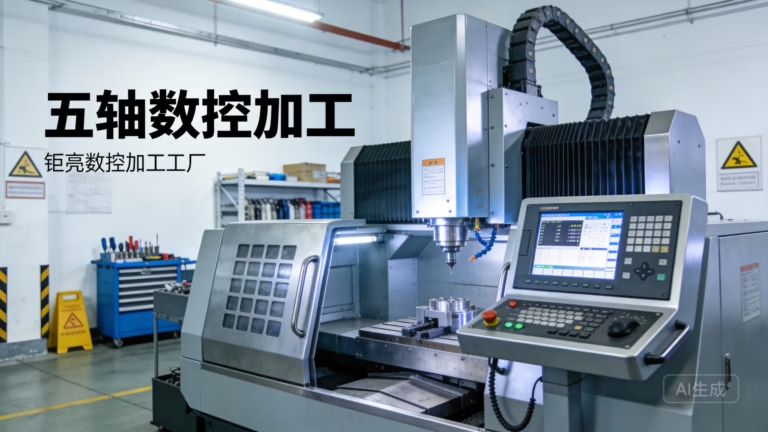
In the realm of precision parts machining, Plexiglas—also known as acrylic or PMMA—presents a unique set of challenges that can transform a straightforward CNC project into a costly disaster if not approached with the right techniques. As a manufacturing engineer with years of hands-on experience, I’ve witnessed countless batches of acrylic parts ruined by chipping, melting, cracking, and dimensional inaccuracies. These failures aren’t just frustrating; they represent wasted material, lost production time, and damaged client relationships. Understanding the fundamental techniques for CNC machining Plexiglas is not optional—it’s essential for any precision machining operation that aims to deliver consistent, high-quality results.
The optical clarity, weather resistance, and excellent machinability of Plexiglas make it a preferred material for applications ranging from automotive lighting components and medical device windows to architectural displays and signage. However, its thermoplastic nature and sensitivity to heat and stress require a fundamentally different machining approach compared to metals or even other plastics. This article draws from real-world production experience and industry best practices to outline five indispensable techniques that will help you avoid the most common and expensive mistakes in CNC Plexiglas machining.
Whether you are a seasoned CNC operator looking to refine your acrylic machining processes or an engineering manager evaluating potential manufacturing partners, these techniques will provide a practical framework for achieving superior results. At GreatLight CNC Machining, where we operate state-of-the-art five-axis CNC machining centers and maintain ISO 9001:2015 certification, we have developed and refined these approaches over more than a decade of precision manufacturing. The insights shared here reflect the collective expertise of our engineering team and our commitment to solving complex manufacturing challenges for clients in automotive, aerospace, medical devices, and beyond.
Technique 1: Tool Geometry and Material Selection—The Foundation of Chip-Free Machining
The single most critical factor in successful CNC Plexiglas machining is selecting the right cutting tools. Standard metal-cutting tools, with their positive rake angles and sharp cutting edges, often destroy acrylic workpieces by inducing excessive heat and causing catastrophic chipping or melting. Understanding the specific tool requirements for Plexiglas can mean the difference between a flawless transparent part and a scrapped piece of cloudy, cracked plastic.
Why Standard Tools Fail
Metal-cutting end mills and drills are designed to shear through ductile materials, creating continuous chips that carry heat away from the cutting zone. Plexiglas, being a brittle thermoplastic, behaves entirely differently. When subjected to aggressive cutting geometries, the material tends to fracture ahead of the cutting edge, creating subsurface cracks and edge chipping. Moreover, the heat generated by improper tool geometry can quickly raise the local temperature above Plexiglas’s glass transition temperature of approximately 105°C, causing the material to soften, melt, and re-solidify in undesirable ways.
Recommended Tool Specifications
For optimal Plexiglas machining, tools should feature:
Geometry Characteristics:
Zero or negative rake angle: Reduces the tendency of the tool to “dig in” and fracture the material
Polished flutes: Minimizes friction and heat generation while improving chip evacuation
Single or double flute designs: Provides ample chip clearance and reduces heat buildup
Helix angles between 10° and 15°: Lower helix angles produce less upward force on the workpiece
| Tool Material | Suitable for Plexiglas | Key Advantages | Recommended Applications |
|---|---|---|---|
| Carbide (Micrograin) | Excellent | High wear resistance, excellent edge sharpness, good heat dissipation | High-volume production, tight tolerances |
| High-Speed Steel (HSS) | Good | Lower cost, easier to sharpen, sufficient for small batches | Prototyping, occasional runs |
| Diamond-Coated Carbide | Superior | Extreme hardness, excellent surface finish, longest tool life | Production runs with stringent optical clarity requirements |
Practical Tip: When milling Plexiglas with a 3-flute or 4-flute end mill, reduce feed rates by 30-40% compared to aluminum cutting parameters. The additional flutes create more friction without proportional material removal benefits.
Tool Sharpness and Edge Preparation
Unlike metal cutting where tool wear is gradual and predictable, a dull tool in Plexiglas machining causes immediate and catastrophic results. The dull cutting edge rubs rather than cuts, generating excessive heat that melts the material. Chips that should be cleanly cut become welded to the tool and workpiece, creating burned spots and rough surfaces.
GreatLight CNC Machining’s experience shows that tools specifically labeled for “acrylic” or “plastic” machining typically outperform general-purpose tools. We regularly inspect cutting edges under magnification and replace tools at the first sign of wear, often long before they would be considered worn for metal applications.
Technique 2: Optimal Cutting Parameters—Balancing Speed, Feed, and Depth
Finding the sweet spot for cutting parameters in Plexiglas machining requires understanding the interplay between spindle speed, feed rate, and depth of cut. Unlike metal machining where higher speeds generally mean faster material removal, Plexiglas behaves optimally within a relatively narrow parameter window. Deviating from this window invites the three most common defects: melting, chipping, and poor surface finish.
The Speed-Feed Relationship
The fundamental principle in Plexiglas machining is to maintain a consistent chip load while controlling heat generation. This translates to:
For Milling Operations:
Spindle Speed: 8,000 to 15,000 RPM for standard carbide tools (larger diameters at lower end)
Feed Rate: 0.05 to 0.15 mm per tooth, adjusted based on tool diameter and cutting depth
Axial Depth of Cut: 0.5 to 2.0 mm for finishing passes; up to 6 mm for roughing
Radial Engagement: 30-50% of tool diameter for finishing; up to 70% for roughing
For Drilling Operations:
Spindle Speed: 3,000 to 8,000 RPM depending on hole diameter
Peck Depth: 0.5 to 1.0 mm per peck
Chip Clearing: Full retraction every 2-3 pecks
Avoiding the “Melt Zone”
The most common error operators make is running Plexiglas at the same spindle speeds they would use for aluminum. At 20,000+ RPM, even with proper feeds, the cumulative friction heat can quickly exceed the material’s melting point. This manifests as:
White, cloudy areas around machined features
Chips that stick to the workpiece
A characteristic burnt-plastic smell
Rough, “gummy” surface finish
Compensation Strategy: If you must use higher spindle speeds due to machine limitations:
Increase feed rate proportionally to maintain proper chip load
Use compressed air or mist coolant directed at the cutting zone
Reduce radial engagement in finishing passes
Consider climb milling to reduce heat generation at the tool exit point
The Science of Chip Thickness
Maintaining the correct chip thickness is perhaps the most overlooked parameter in Plexiglas machining. Too thin a chip causes rubbing and melting because the material is not being sheared—it’s being burnished. Too thick a chip causes edge chipping and breakage. The optimal chip thickness for Plexiglas typically falls between 0.05 mm and 0.15 mm per tooth.
Practical Guideline: For a 6 mm diameter end mill running at 12,000 RPM with two flutes:
Target chip load: 0.08 mm/tooth
Feed rate calculation: 12,000 RPM × 2 flutes × 0.08 mm = 1,920 mm/min
Adjust up or down based on observed chip formation and surface quality
Technique 3: Workholding and Fixturing—Eliminating Stress-Induced Cracking
Plexiglas’s susceptibility to stress cracking makes workholding a critical consideration. Unlike metals that can be securely clamped with significant force, acrylic parts require a gentler approach that distributes clamping pressure evenly. Improper fixturing is one of the leading causes of part rejection in acrylic machining, often resulting in hairline cracks that appear hours or days after machining.
Understanding Stress Concentration
When a clamp applies concentrated force to a Plexiglas workpiece, the material experiences localized stress that may not immediately show visible damage. However, as the machining process removes material and redistributes internal stresses, or as the part experiences thermal cycling during use, these stress concentrations can initiate cracks that propagate through the part. This delayed failure is particularly problematic because it often occurs after the part has been delivered to the customer.
Recommended Workholding Solutions
Vacuum Fixturing:
This is the gold standard for Plexiglas machining, especially for flat parts and sheet stock. Vacuum chucks distribute holding force evenly across the entire part surface, eliminating stress concentration points entirely.
Vacuum Level: 25-28 inHg minimum for reliable holding
Seal Design: Rubber gaskets or O-ring grooves around the part perimeter
Surface Preparation: Clean, flat chuck surface with no debris that could create pressure points
Soft Jaw Clamping:
When vacuum fixturing is not feasible, soft jaws provide the next best solution.
Jaw Material: Aluminum or Delrin (acetal) jaws machined to match part contours
Clamping Force: Reduce to 30-50% of normal metal clamping force
Pressure Distribution: Use wide, flat contact surfaces; avoid point contacts
Adhesive Fixturing:
For complex geometries or second-operation work, temporary bonding can be effective.
Adhesive Types: Cyanoacrylate (super glue) or hot-melt adhesives with low shrinkage
Release Method: Heat, solvent, or mechanical separation depending on adhesive
Clean-Up: Remove all adhesive residues immediately to prevent chemical attack on acrylic
Fixturing for Thin-Walled Parts
Thin-walled acrylic parts present special challenges because they lack the structural rigidity to withstand even moderate clamping forces. For these components:
Support Strategy: Fill cavity areas with low-melting-point alloys or wax that can be removed after machining
Clamping Sequence: Tighten clamps gradually in a crisscross pattern to avoid warping
Backup Support: Use custom fixtures that support the part from behind, preventing deflection during cutting
GreatLight CNC Machining has developed specialized vacuum fixture designs for thin acrylic lenses and medical device windows, achieving consistent dimensional accuracy on parts as thin as 0.5 mm without stress cracking. Our engineering team analyzes each part’s geometry to determine the optimal workholding approach, often combining multiple techniques for complex components.
Technique 4: Cooling and Chip Evacuation—Preventing Thermal Damage
Heat management is arguably the most critical aspect of successful Plexiglas machining. Unlike metals that conduct heat efficiently and allow coolants to dissipate thermal energy, Plexiglas is an excellent thermal insulator. Heat generated at the cutting edge accumulates rapidly, leading to material softening, melting, and dimensional instability. Effective cooling and chip evacuation strategies must be integrated into every Plexiglas machining operation.
The Cooling Dilemma: Flood Coolant vs. Air vs. Mist
Each cooling method has distinct advantages and limitations when applied to Plexiglas:
Flood Coolant:
Advantages: Excellent heat dissipation, lubricates cutting action, flushes chips effectively
Disadvantages: Water-based coolants can cause stress cracking in some acrylic formulations; coolant residue requires thorough cleaning; potential for thermal shock if coolant temperature differs significantly from workpiece temperature
Recommendation: Use only water-soluble coolants specifically formulated for plastics; maintain coolant temperature within ±5°C of workpiece temperature
Compressed Air:
Advantages: No chemical interaction with material, no cleanup required, prevents chip re-welding
Disadvantages: Less effective heat removal than liquid coolants, can blow fine chips into machine ways and bearings
Recommendation: Use in combination with proper chip collection; 80-100 PSI directed at the cutting zone
Mist Coolant:
Advantages: Moderate heat removal, minimal mess, good lubrication
Disadvantages: Potential for uneven cooling; mist particles can create fog in work area
Recommendation: Vegetable-based or synthetic coolants formulated for plastics; apply as fine mist rather than heavy spray
Chip Evacuation Strategies
In Plexiglas machining, chips that remain in the cutting zone become heat sources and potential sources of surface damage. Effective chip evacuation requires:
For Milling Operations:
Use tools with polished flutes to reduce chip adhesion
Program chip-clearing movements (peck milling) for deep cavities and slots
Use through-spindle coolant or air blast when available
Maintain adequate radial engagement to prevent chip recutting
For Drilling Operations:
Peck drilling is mandatory for depths exceeding 2 × tool diameter
Retract fully between pecks to break and clear chips
Use parabolic flute drills designed for chip evacuation
Avoid G73 (high-speed peck) cycling; use G83 (full retraction) instead
For Tapping Operations:
Form taps (thread forming) produce no chips and are preferred for Plexiglas
If cutting taps must be used, maintain peck depth under 0.5 × thread pitch
Use tapping fluid specifically formulated for plastics
Temperature Monitoring During Machining
For critical applications or challenging geometries, direct temperature monitoring can prevent thermal damage:
Infrared Thermometers: Non-contact measurement of workpiece surface temperature
Thermocouple Embedding: For production runs, embed thermocouples in fixturing near cutting zones
Alert Threshold: Stop machining if workpiece temperature exceeds 70°C (80°C absolute maximum)
Practical Observation: At GreatLight CNC Machining, we have established that maintaining workpiece temperature below 60°C during roughing operations and below 50°C during finishing passes virtually eliminates thermal defects in Plexiglas parts. This commitment to thermal management has significantly reduced our scrap rate for optical-grade acrylic components.
Technique 5: Post-Machining Stress Relief and Surface Finishing—Achieving Optical Clarity
The final technique addresses what happens after the cutting stops. Even perfectly machined Plexiglas parts contain residual stresses induced by the cutting process. If not addressed, these stresses can lead to delayed cracking, dimensional changes, and surface degradation. Additionally, achieving the optical clarity that makes acrylic the material of choice for transparent applications requires specific post-processing steps.
Annealing for Stress Relief
Thermal annealing is the most effective method for relieving internal stresses in machined Plexiglas parts. The process involves controlled heating and slow cooling that allows molecular chains to relax and stresses to equalize.
Annealing Cycle Parameters:
| Phase | Temperature | Duration | Cooling Rate |
|---|---|---|---|
| Ramp Up | Room to 80°C | 1 hour per 5 mm thickness | N/A |
| Soak | 80°C ± 2°C | 1 hour per 5 mm minimum | N/A |
| Cool Down | 80°C to 50°C | 2 hours minimum | 15°C/hour maximum |
| Final Cool | 50°C to Room | Ambient conditions | Free cool (covered) |
Critical Notes:
Do not exceed 85°C to avoid part distortion
Parts must be supported on flat surfaces to prevent sagging
Annealing should be performed before any critical finishing operations
For parts requiring optical clarity, annealing is non-negotiable
Alternative Stress Relief Methods
When thermal annealing is impractical (e.g., for assemblies with heat-sensitive components):
Room Temperature Aging: Allow parts to rest for 24-72 hours before final inspection and finishing
Ultrasonic Vibration: Low-frequency vibration can accelerate stress relaxation
Chemical Dipping: Controlled exposure to methylene chloride vapor or liquid can relieve surface stresses (requires safety precautions and careful process control)
Surface Finishing for Optical Clarity
Machined Plexiglas surfaces are typically translucent or hazy immediately after cutting. Restoring optical clarity requires progressive refinement:
Sandpaper Sequence:
Wet sand with 400 grit (remove tool marks, 60-120 seconds)
Wet sand with 600 grit (remove 400 grit scratches, 60-90 seconds)
Wet sand with 800 grit (prepare for polishing, 45-60 seconds)
Wet sand with 1000 grit (final sanding, 30-45 seconds)
Buffing and Polishing:
Use cotton or flannel buffing wheels at 1,500-2,500 RPM
Apply specialized acrylic polishing compounds (avoid waxes with abrasive fillers)
Maintain light, consistent pressure to avoid heat buildup
Final polish with clean wheel and no compound produces the best optical clarity
Flame Polishing (For Edges Only):
Use a hydrogen-oxygen flame or propane torch with proper control
Quick passes (1-2 seconds per linear inch) prevent overheating
This technique is advanced; improper execution causes bubbling or burning
Always practice on scrap material before applying to finished parts
Quality Verification
After post-processing, verify optical quality using:
Visual Inspection: Under strong backlighting, look for haze, scratches, or fingerprints
Surface Profilometry: Measure Ra (surface roughness) value; optical clarity typically requires Ra < 0.1 μm
Stress Birefringence: Use polarized light to check for residual stress patterns
Dimensional Verification: Measure critical features after stress relief to confirm no distortion occurred
Conclusion: Integrating Proven Techniques for Manufacturing Excellence
Mastering these five essential CNC Plexiglas techniques—proper tool selection, optimized cutting parameters, stress-free workholding, effective thermal management, and comprehensive post-machining processing—transforms acrylic machining from a high-risk operation into a reliable, repeatable manufacturing process. Each technique addresses specific failure modes that plague less experienced operators, and implementing them systematically significantly reduces scrap rates, improves delivery times, and enhances customer satisfaction.
As with any precision manufacturing process, the key lies not in any single technique but in their integrated application. Tooling decisions affect parameter selection; workholding choices influence thermal management strategies; and post-processing requirements should be anticipated during the initial process planning phase. Experienced manufacturers develop intuitive understanding of these interconnections, allowing them to adapt their approach to the unique demands of each project.
For organizations seeking to implement these techniques or evaluate potential manufacturing partners, consider these criteria:
Evaluating Supplier Capability:
Does the supplier maintain dedicated plastic-machining tooling separate from metal-cutting tools?
Can they demonstrate documented process parameters for acrylic machining?
Do they have experience with vacuum fixturing and other stress-free workholding methods?
What quality checks do they perform for stress cracking and optical clarity?
The Value of Experienced Partners:
GreatLight CNC Machining has invested heavily in developing specialized expertise for Plexiglas and other engineering plastics. Our fully equipped facility includes dedicated work cells for plastic machining, with tooling, coolant systems, and chip management optimized specifically for thermoplastic materials. Our engineering team has successfully delivered thousands of acrylic components for demanding applications, from medical diagnostic equipment windows requiring optical-grade clarity to automotive lighting components demanding long-term environmental resistance.
When you choose a partner with real operational capabilities, not just paper qualifications, you gain access to accumulated knowledge that no single operator can develop independently. Our ISO 9001:2015 quality management system ensures that these techniques are documented, controlled, and continuously improved. Our ISO 27001 compliance provides data security for your intellectual property, and our IATF 16949 certification demonstrates our commitment to automotive industry quality standards.
By embracing these five essential techniques and partnering with a manufacturer that has made them part of their standard operating procedures, you eliminate the guesswork and variability that plague Plexiglas machining. The result is consistent, high-quality parts that meet specifications the first time, every time. This is the standard of precision manufacturing that modern industries demand, and it is the standard that GreatLight Metal delivers every day.



















