Interference fittings depend on the amount of interference after the associated parts are assembled to achieve a tight connection. After assembly. Due to the elastic deformation of the material, pressure is generated between the contact surfaces. Therefore, there is considerable friction force between the contact surfaces to transmit torsional or axial force during operation. The interference fit assembly is generally a fixed, non-detachable connection. Interference fit assembly methods include: (1) hand hammering method, (2) press pressing method (3) cold fitting method, (4) hot fitting method;
1) Inspection of interference mounting parts before assembly
Interference-fit parts should be re-inspected before assembly. And keep records.
(1) The amount of interference must conform to the requirements of the process drawing or document.
(2) The vertical gap of the end face of the impeller or ring concerned which is in contact with the shoulder of the shaft, together with the green end face of the impeller as a reference assembly, and the hole must be within the range specified in the drawing.
(3) Round roots, chamfers, etc. relevant parts should not affect assembly.
(4) There are ridges, rust spots or scratches on the corresponding surface.
(5) When the hole of the containing component is a blind hole, the contained component must have vent holes or grooves, otherwise assembly is not allowed.
(6) Mounting parts with keyed connections. Before assembly, the positions of shaft grooves, hole grooves and grinding keys must be rechecked, and assembly can only be carried out after they are correct.
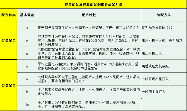
2) Assembling the interference fittings The assembly of the interference fittings is shown in the table below.
Manual tapping method:
Assembly of small parts suitable for transition adjustments
1. There should be no scratches on the surface of large assembly parts.
2. When assembling, the surface of the included parts should be lubricated with engine oil.
3. When installing, soft metal or hard non-metallic materials should be used as protective lining.
4. During the assembly process, the contained part and the containing part must be coaxial and no tilt is allowed.
5. The assembled parts should be close to the relevant limit shaft shoulders, etc., and the gap should not be greater than 0.05mm.
Pressing method:
Suitable for use at room temperature. Assembly of medium and small parts with small interferences
1. The entry end of the press-fit part must be made with an inverted cone. If there is no stipulation in the drawing, the reverse taper must be carried out with a taper of 1:150. The duration is 10% to 15% of the total duration of the match.
Pressing force F empirical calculation formula F=KiL×104
in the formula
i – actual measured interference quantity mm
L-mounting length mm
K——Coefficient that takes into account factors such as the material and size of the installed parts
The value of the K coefficient is 1.5 ~ 3
2. When the solid shaft and non-through parts are press fitted, it is allowed to process an exhaust plane with a depth of more than 0.5mm on the surface of the coupling journal.
3. The contact surface of the interference fit parts. Lubricating oil (lead oil mixed with engine oil) is required before press assembly.
4. When press fitting, the center line of the constraint must be coaxial with the center line of the containing part and the contained part. For thin shafts, the coaxiality of the stress axis and the parts must be strictly controlled.
5. Pressing the wheel and shaft. Never let the rim bear the force alone
6. After press-fit, the shaft shoulder must be tightened. The gap is less than 0.05mm
7. When using heavy objects for pressure mounting, pressing should be smooth and unhindered. Any anomaly must be analyzed to avoid crushing of parts.
8. When using a hydraulic machine for installation. The pressing force F should be checked to ensure that the pressure generated by the press should be 1.5 to 2 times the pressing force F
9. When using a hydraulic press for installation, pressure changes should be recorded.
1) Pressure changes should be smooth and analysis should be performed when abnormalities occur and no parts should be crushed.
2) When the design requires maximum pressure, it should reach the specified value and should not be too large or too small.
3) When installing a mechanical press, the speed should not be too fast. The pressing speed is 2-4 mm/s.
Do not exceed 10 mm/s
Hot loading method:
Suitable for assembling parts with large interferences
1. Make preparations before hot loading. To ensure the smooth running of the hot loading process
(1) Formula for calculating heating temperature T
T=(σ+d)/ad+T (℃)
In the formula, d – nominal diameter of the fit (mm)
a-Linear expansion coefficient of heating parts material (1/℃) Commonly used materials
Please refer to the corresponding manual for the linear expansion coefficient of the material.
σ-Maximum interference of adjustment size mm
δ-Hot mounting space required (mm) When d<200mm,
δTake(1″2)p
When d≥200mm,
δ takes (0.001″0.0015)d2
(2) The heating time is estimated based on the fact that a workpiece with a thickness of 10 mm should be heated for 10 minutes. The thickness value is calculated based on the smaller of the axial and radial dimensions of the part.
(3) The holding time is estimated at 1/4 of the heating time
2. Container heating. Once the expansion reaches the required amount, the contact surface of the packaging and packaging should be quickly cleaned and then immediately hot mounted. The operation must be rapid and precise, and the hot installation is in place at the same time, and no breaks are allowed in the intermediate coating. If an anomaly occurs, forced loading is not allowed. The fault must be rectified, reheated, then hot charged.
3. After hot-mounted parts, reliable measurements such as pulling, pressing and lifting are used to bring the hot-mounted parts closer to the axial locating surface of the enclosed part. Once the parts have cooled, their clearance should not exceed 1000 of the connection length.
4. When installing copper sleeves in steel parts, the containing parts can only be hot-mounted once. After installation, they must not be reheated as hot secondary parts.
5. When ring structure gears are hot assembled. It was heated once when installing the ring gear. When hot installing the shaft, it must be heated a second time. Generally, oil bath heating should be used. If conditions are limited, electric furnace heating can also be used, but the rate of temperature increase must be strictly controlled to make the temperature uniform. And the distance between the outer surface of the work surface and the oven wire is more than 300mm, otherwise its use is not allowed.
6. Use an oil bath for heating and control the oil temperature at 10°C or 20°C below the flash point of the oil. It is never allowed to use the flash point of the oil or above the flash point. Flash points of commonly used oils are shown in Table 7-86.
7. When using inductive heaters for heating, the equipment specifications should be selected appropriately, and the equipment operation procedures should be strictly followed.
Cold installation method:
Suitable for parts assembly where containing parts cannot be heated or where heating may cause changes in part accuracy, material structure or affect mechanical parts.
1. When loading cold
l TI calculation formula for freezing temperature
T1=2σ/a1d (℃)
in the formula
σ—maximum interference (mm)
d—Outer diameter of contained component (mm) a1—Linear expansion coefficient when contained component is cooled Please refer to the corresponding manual for the linear expansion coefficient of commonly used materials during cooling.
Formula for calculating freezing time t
t= a’δ’ (6~8)(mm)
For material-related coefficients in the formula, please refer to the corresponding manual.
Characteristic dimensions of the frozen piece. That is, the maximum section radius or wall thickness of the part (mm)
1) Calculate the freezing temperature T according to the formula
2) When selecting a refrigerant, the temperature of the refrigerant should be lower than the required freezing temperature T1 of the contained component. When the diameter of the component contained is greater than φ50 mm, liquid oxygen or liquid nitrogen is preferred. manual corresponding to the refrigerant temperature value.
3) Calculate freezing time
2. When liquid oxygen is used as a refrigerant in a cold installation. It is strictly forbidden to have flammable materials and fire nearby
3. Operators should wear labor protection equipment, long-sleeved clothing, long pants, protective glasses and leather gloves. Attach the canvas legs. make it work
4. There should be ventilation holes in the refrigerant tank and the cooler, and they should not be blocked when in use. To avoid explosion caused by increased pressure. The inside of the box must be clean and the cooler must be placed stably and reliably.
5. Refrigerant should be drawn off as required and care should be taken when pouring to avoid spills and splashes. The liquid level in the cooler should be maintained at a height sufficient to submerge the contact surface of the parts, but it should not be too full and should be 80 cm below the top surface of the box lid. Volatile refrigerant must be replenished in time
6. Use tools to put in or remove parts from the cooler, tighten them with pliers or tie them with wires in advance. Do not pick up or place parts directly with your hands to avoid burns
7. Freezing time is calculated from the time the parts are immersed in the refrigerant. There is a “boiling” phenomenon of strong cracks in the early stages of immersion of the parts. Then it gradually weakens and even disappears. When it first stops, it just means that the temperature difference between the surface of the part and the refrigerant is very small, but it is not completely cold. It must be completely cooled according to the calculated time
8. Once the parts have warmed up. Remove it and immediately place it in the hole in the package. Movements must be quick and precise. Pay attention to concentricity when clamping parts. It should not be tilted. Correct the tilt caused by the installation. Only copper rods or wooden hammers can be used for striking. If it is a copper piece, a wooden hammer should be used.
9. If there are multiple parts to install, remove one part from the cooler, add one part at a time, and refill the refrigerant in time. Close the lid
Daguang focuses on providing solutions such as precision CNC machining services (3-axis, 4-axis, 5-axis machining), CNC milling, 3D printing and rapid prototyping services.


