
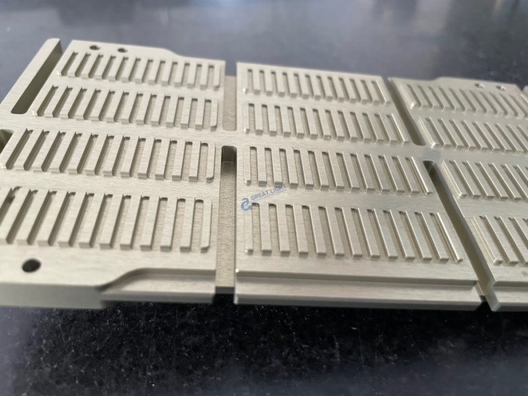
In the world of modern manufacturing, where tolerances are measured in microns and geometries grow increasingly complex, a fundamental question underpins the creation of nearly every advanced component: How can work CNC machine? The answer is a fascinating synergy of digital instruction, mechanical precision, and automated control, transforming blocks of raw material into intricate, high-value parts. For clients seeking precision parts machining and customization, understanding this process is key to unlocking its full potential for their projects.
At its core, a CNC (Computer Numerical Control) machine is a subtractive manufacturing tool that removes material from a solid block (workpiece) to create a desired shape. The “how” involves three inseparable elements: the digital brain (the program), the physical executor (the machine tool), and the strategic interface (the human operator/engineer).
H2: The Digital Blueprint: From CAD to G-Code
The journey begins far from the factory floor, within a Computer-Aided Design (CAD) software. An engineer designs a 3D model of the part, defining every curve, hole, and surface. This model is then translated into manufacturing instructions through Computer-Aided Manufacturing (CAM) software.
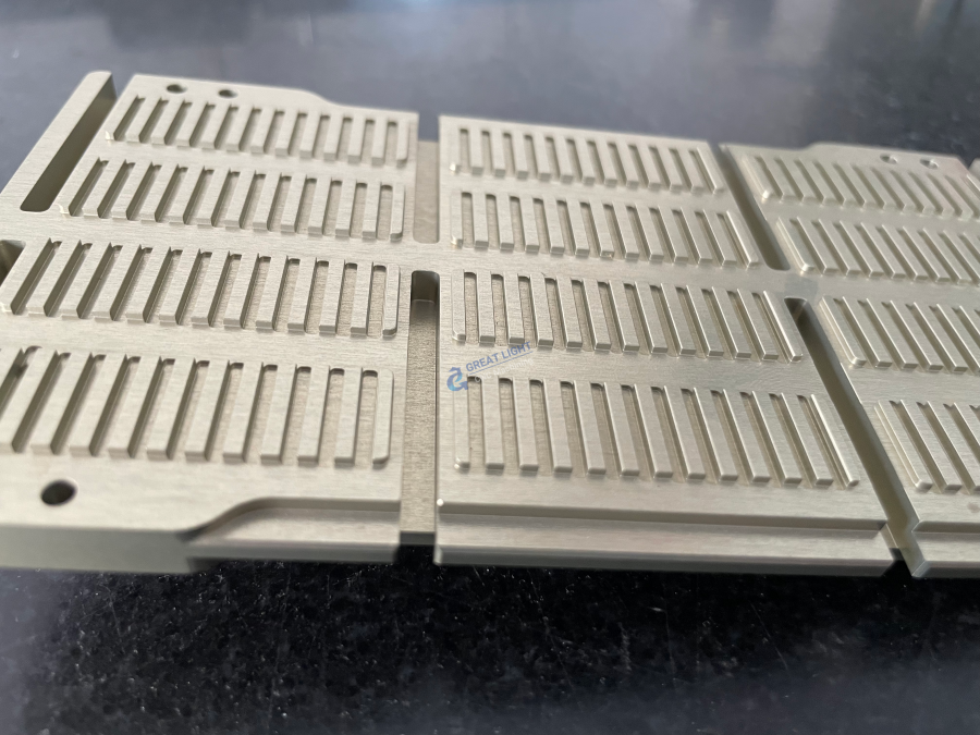
The CAM software acts as a strategic planner. It determines:
Toolpaths: The precise routes the cutting tool will take.
Tool Selection: Which cutter (drill, end mill, ball nose) to use for each operation.
Cutting Parameters: The spindle speed (RPM), feed rate (how fast the tool moves), and depth of cut.
Order of Operations: The logical sequence to machine features efficiently and accurately.
The output of this planning is a text file containing G-code—a standardized, albeit complex, programming language. Each line of G-code is a command, such as G01 X10.5 Y20.0 F200, which tells the machine to move in a straight line (G01) to coordinates X=10.5mm and Y=20.0mm at a feed rate (F) of 200 mm per minute. This code is the literal set of instructions that “tell” the CNC machine how to work.
H2: The Physical Executor: Anatomy of a CNC Machine
While mills and lathes are the most common, the principles apply across CNC types. Key subsystems bring the G-code to life:
Controller & Drives: This is the machine’s “central nervous system.” It reads the G-code, interprets the commands, and sends electrical signals to the drive motors.
Drive Motors & Ball Screws: Servo or stepper motors convert the electrical signals into precise rotational motion. This rotation turns ball screws—high-accuracy threaded rods that convert rotation into linear motion along the machine’s axes.
The Machine Axes: This defines the machine’s freedom of movement. A standard 3-axis CNC mill moves the tool in X (left-right), Y (front-back), and Z (up-down). More advanced machines, like the 5-axis CNC machining centers at GreatLight CNC Machining Factory, add rotational axes (typically A and B), allowing the tool to approach the workpiece from virtually any angle in a single setup. This is crucial for complex aerospace impellers or medical implants.
Spindle & Tooling: The spindle is the high-speed motor that rotates the cutting tool. A Tool Changer (ATC) automatically swaps tools from a carousel as programmed, enabling operations like drilling, roughing, and finishing without manual intervention.
Workholding & Table: The workpiece must be immobilized with extreme rigidity. This is achieved using vises, clamps, or custom fixtures bolted to the machine table.
H2: The Symphony of Motion: How Axes and Tools Collaborate
Imagine machining a simple aluminum bracket with a hole and a pocket.
Step 1: Setup & Zeroing. The operator loads the raw material, secures it in a vise, and installs the required tools in the ATC. Using a probe or manual method, they set the work coordinate system (WCS), telling the machine, “This specific point on the block is your X0, Y0, Z0 reference for all movements.”
Step 2: Program Execution. The operator initiates the program. The controller reads the first lines of G-code.
The ATC selects a flat end mill and moves to a safe start position.
The spindle accelerates to 12,000 RPM.
Following the toolpath, the machine rapidly positions the tool above the material (rapid traverse, G00), then plunges to a specified depth to begin cutting the outer contour (linear interpolation, G01).
The drives precisely coordinate X and Y axis movements, guiding the tool along the programmed path while the spindle removes material in chips.
Step 3: Feature Completion. After roughing the pocket, the program might call for a tool change. The ATC swaps in a smaller tool for fine details, then a drill for the hole. Coolant floods the cutting area to manage heat and clear chips. Every move—every thousandth of a millimeter—is dictated by the pre-planned code.
Step 4: Completion. The tool retracts, the spindle stops, and the machine signals completion. The operator unclamps a finished part that is a physical manifestation of the original digital file.
H2: Advanced Capabilities: The 5-Axis Advantage
For clients pushing the boundaries of design, understanding how a 5-axis CNC machine works reveals a quantum leap in capability. Unlike 3-axis machines, where the tool orientation is fixed, 5-axis machines can dynamically tilt the cutting tool or the workpiece itself. This allows for:
Single-Setup Machining: Complex parts can be completed in one fixture, eliminating errors from re-positioning and drastically reducing lead time.
Access to Complex Geometry: Undercuts, deep cavities, and compound curved surfaces (like those on turbine blades or mold cores) become machinable.
Improved Tool Life & Surface Finish: By tilting the tool, the optimal cutting edge can be engaged, and higher spindle speeds can be used more effectively, leading to better finishes and longer tool life.
This advanced capability is central to the services at GreatLight CNC Machining Factory. Their expertise in programming and operating sophisticated 5-axis equipment transforms how challenging workpieces are machined, providing clients with integrated solutions for parts that would be impossible or prohibitively expensive using conventional methods.
Conclusion: The Convergence of Digital Fidelity and Mechanical Precision
So, how can work CNC machine? It works by being a flawless interpreter of digital intent, a tireless executor of microscopic movements, and a versatile platform capable of handling materials from plastics to superalloys. The process marries the abstract world of software with the concrete world of physics, governed by principles of precision engineering. For businesses looking to leverage this technology, the choice of manufacturing partner is critical. It requires not just machines, but the deep engineering support, process knowledge, and quality systems to ensure the digital blueprint is realized with absolute fidelity. Partners like GreatLight CNC Machining Factory, with their full-process chain from advanced 5-axis machining to comprehensive post-processing, embody this principle, turning the sophisticated “how” of CNC machining into the simple “done” for their clients.
FAQ: Frequently Asked Questions
Q1: What’s the main difference between 3-axis, 4-axis, and 5-axis CNC machining?
3-Axis: The tool moves in three linear directions (X, Y, Z). Ideal for prismatic parts with features on one main face.
4-Axis: Adds one rotational axis (usually the A-axis), allowing the workpiece to rotate. Excellent for machining features around a cylinder, like camshafts or helical gears.
5-Axis: Adds a second rotational axis (e.g., B-axis), enabling the tool to approach the workpiece from any direction. Essential for complex, free-form geometries common in aerospace, automotive, and medical sectors. GreatLight CNC Machining Factory specializes in harnessing 5-axis technology for maximum efficiency and complexity.
Q2: How do you ensure the precision and accuracy promised in CNC machining?
Precision is systemic. It starts with high-grade, well-maintained machines with rigid frames and precise ball screws. Environmental controls (temperature) minimize thermal expansion. Crucially, it involves:
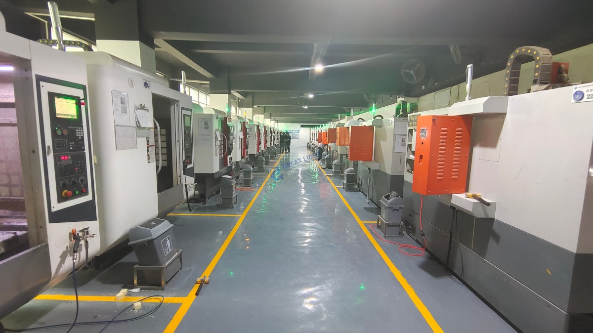
In-Process Probing: Tools like touch probes automatically measure tool length and part features, compensating for wear or thermal drift in real-time.
Post-Process Metrology: Finished parts are verified using Coordinate Measuring Machines (CMMs), optical scanners, and surface profilometers against the original CAD model.
Certified Quality Systems: Adherence to standards like ISO 9001:2015 (which GreatLight holds) ensures these measurement and control processes are documented, repeatable, and auditable.
Q3: What materials can be processed using CNC machines?
CNC machining is remarkably material-agnostic. Common categories include:
Metals: Aluminum, Stainless Steel, Titanium, Brass, Copper, Tool Steels, Inconel.
Plastics: ABS, Polycarbonate, PEEK, Nylon, PTFE (Teflon), Delrin.
Composites: Certain machinable composite boards.
Others: Wood, wax (for molding), and some ceramics. The key is selecting the correct tooling, speeds, and feeds for each material’s properties.
Q4: What are the limitations of CNC machining?
While versatile, CNC machining has constraints:
Internal Geometry: It cannot machine internal cavities that are completely enclosed, as the tool must have a path to enter. (This is where 3D printing or assembly becomes complementary).
Sharp Internal Corners: Cutting tools are round, so perfectly sharp internal corners are impossible; a radius equal to the tool’s radius will remain.
High-Volume Part Cost: For very high volumes (e.g., millions of parts), techniques like injection molding or die-casting often become more economical after the initial tooling investment.
Material Waste: Being a subtractive process, it generates chips (swarf), which can be a consideration for expensive materials.
Q5: For a new project, what information should I provide to get an accurate CNC machining quote?
To receive a fast and accurate quote, provide your manufacturing partner with:
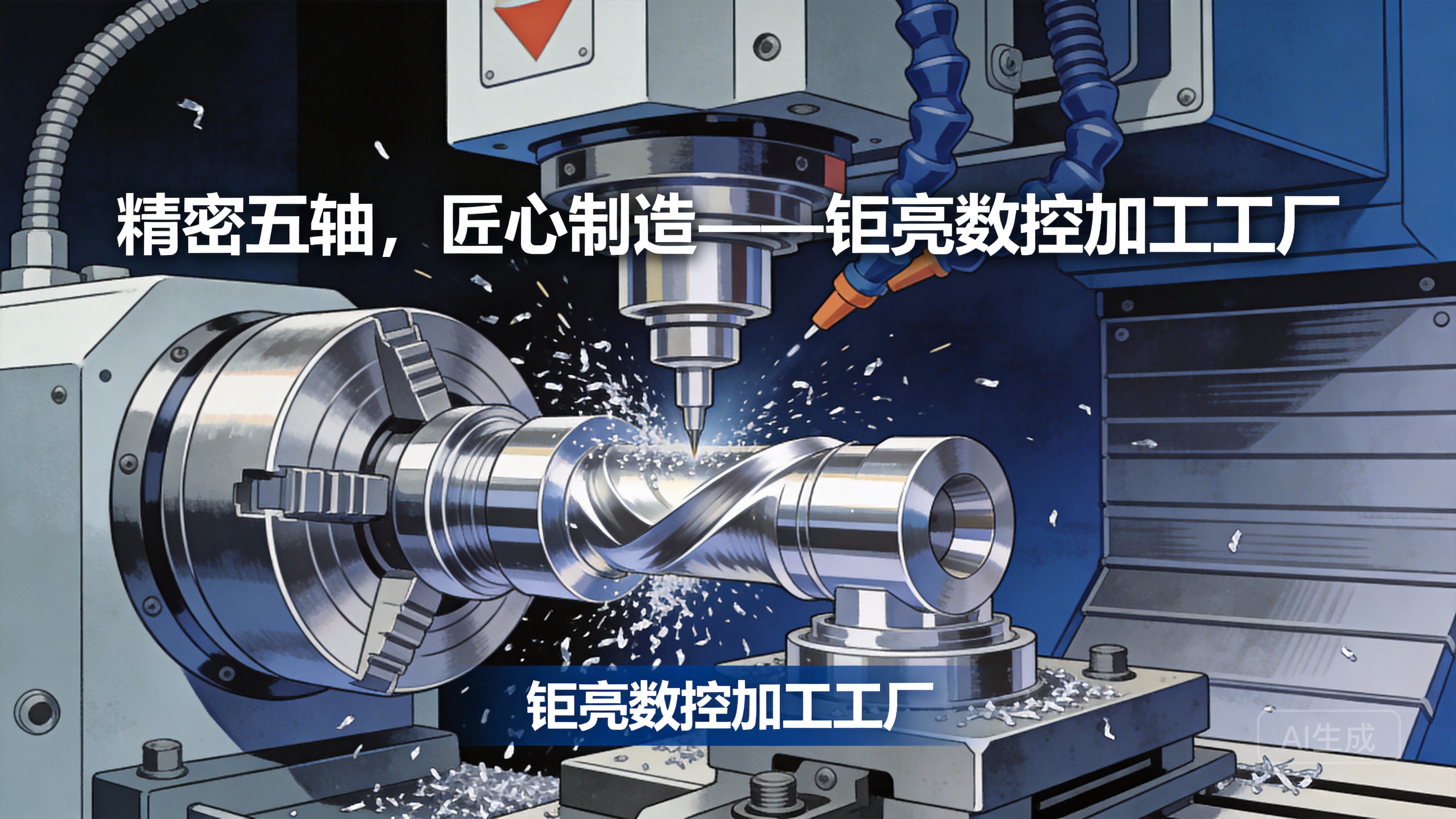
Detailed 2D Drawings or 3D CAD Files (STEP, IGES, SLDPRT, etc.).
Material Specification.
Required Quantity.
Surface Finish Requirements (e.g., Ra 1.6, anodized, powder-coated).
Critical Tolerances (highlight the most important dimensions).
Any Applicable Industry Standards (e.g., AS9100 for aerospace, ISO 13485 for medical).
For more insights into the evolving landscape of precision manufacturing and partnership opportunities, you can follow industry leaders like GreatLight on professional networks such as LinkedIn.



















