
Grbl 4 Axis Mastery: 5 Essential Secrets to Unlock Flawless Multi-Axis Control
The democratization of CNC machining has been one of the most exciting developments in manufacturing over the past decade, and at the heart of countless DIY and small‑scale CNC builds sits an open‑source firmware called Grbl. With the addition of a fourth rotational axis, makers, small workshops, and even advanced prototyping labs can achieve cylindrical engraving, complex indexing, and continuous wrapping operations that were once the exclusive domain of expensive industrial machines. Yet, moving from a basic 3‑axis setup to reliable 4‑axis control introduces a host of challenges that can turn a promising project into a frustrating exercise in scrap material.
If you are looking to wring every last micron of accuracy and drop of productivity out of your Grbl‑based rotary system, you need to understand not just the wiring, but the integration of mechanical calibration, G‑code subtleties, and intelligent process design. At the same time, as a senior manufacturing engineer, I know that many parts eventually outgrow the hobbyist ecosystem and require the uncompromising repeatability of professional precision 5-axis CNC machining services. In this guide, I’ll share five essential secrets that will elevate your Grbl 4‑axis project from “kind of works” to “flawless multi‑axis control,” and along the way, illuminate when it’s wise to partner with an industrial expert to bring your most critical designs to life.
Secret 1: Solidify Your Electronics and Wiring for Noise‑Free 4th Axis Operation
Your physical wiring and controller electronics form the nervous system of the machine, and in 4‑axis work, even a single missed step can scrap a part that has been machining for hours. Grbl handles pulse generation admirably, but the additional stepper motor for the A‑axis draws extra current, introduces more electromagnetic interference (EMI), and demands proper signal integrity.
Grounding and Shielding
Run all stepper motor cables through shielded, twisted‑pair wiring. Connect the shield drain wire to the controller’s earth ground at one end only – this avoids ground loops. Keep motor power cables well separated from limit‑switch and control signal wiring; a mere 5 cm of parallel run can induce enough noise to cause a false limit trigger, especially when the spindle ramps up.
Stepper Driver Configuration
Set the driver current to the motor’s rated phase current and not above 80% of the driver’s continuous rating. Over‑driving a motor might give a bit more torque on the bench, but it causes thermal drift and can overheat the driver during long 4‑axis carving sessions.
Enable mixed decay mode if your driver supports it; this reduces mid‑band resonance that is particularly troublesome with low‑rpm rotary moves.
Configure microstepping appropriately. A 1/8 or 1/16 microstep setting provides smooth motion, but Grbl’s step pulse timing must be checked to ensure the controller can output enough pulses per second at your chosen feedrate. For a 200 step/rev motor, 1/16 microstepping, and a 4:1 harmonic drive rotary table, you can end up with 12,800 steps per revolution, demanding a very high step rate from the Arduino. Always calculate the step frequency at your maximum A‑axis angular velocity and compare it against the Grbl controller’s maximum reliable step rate (typically 30 kHz for an Arduino Uno). If you exceed this, you will experience stalling at speed.
A‑Axis Motor and Drive Coupling
Backlash on the rotary axis starts right at the coupling. Use a high‑quality helical beam coupling or bellows coupling, not a cheap jaw coupler. Even 0.05° of rotational play at the coupling translates into a significant surface finish artifact. After mounting, power the motor with holding current and gently twist the rotary table by hand; any perceptible movement must be eliminated.
Secret 2: Perfect Homing and Work Offsets – The Foundation of Multi‑Axis Precision
In 3‑axis milling, a homing error might shift a pocket by a fraction of a millimeter – annoying, but often harmless. In 4‑axis work, an incorrectly set A‑axis zero can wrap a pattern that is supposed to meet at 360° into an ugly misalignment that shouts “scrap” from across the room. Reliable homing and the disciplined use of work coordinate offsets are non‑negotiable.
Homing the Rotary Axis
Most Grbl configurations use a simple NC microswitch for the A‑axis home. Position the switch such that it trips at a repeatable angular position, ideally using a hardened detent or a precision‑ground flat on the rotary table’s shaft. Debounce the switch in hardware (a small capacitor across the signal and ground) and in Grbl by setting the debounce duration ($26) to something like 25–50 ms. After homing, I recommend issuing an A‑axis move of a few degrees away, then re‑homing three times while measuring the repeatability with a test indicator. The variation must be less than half of your minimum intended angular tolerance, or you’ll be chasing ghost offsets.
Work Coordinate System Setup
Use G54–G59 for different parts or fixtures. Never program moves directly in the machine coordinate system (G53) except for homing.
For cylindrical parts, I establish the A‑axis work zero by touching off the top of the stock at two angular orientations 180° apart, calculating the center, and then setting G54 A‑offset to zero when the fixture’s reference flat is parallel to the machine table.
Document your offset method in a setup sheet. Nothing wastes more time than re‑indicating a part because a co‑worker or your future self cannot remember the dial‑indicator dance you performed three weeks ago.
Persistent Offsets and Power‑Loss Recovery
Grbl’s default behavior is to clear the workspace after a power cycle unless you’ve saved the parameters with the proper EEPROM settings. Frequently use G10 L2 P1 X... Y... Z... A... to program offsets and verify with $# after a restart. This tiny discipline will save your production runs.
Secret 3: Unlock Continuous 4‑Axis Toolpaths with Clever G‑Code Generation
Many CAM packages offer a “4‑axis indexing” strategy where the A‑axis positions the part, machining happens in 2.5D, then the A moves to the next index. That is useful, but true mastery comes from simultaneous 4‑axis continuous machining – wrapping a complex surface around a cylinder or creating a sculpted helical groove. Getting clean G‑code out of Grbl for such paths requires you to understand how the controller interprets feed rates and how to avoid stuttering caused by tiny linear segments.
Feed Rate Calculation – The Key to Smooth Motion
By default, Grbl interprets the feed rate command (F) in units per minute in the linear domain (mm/min) and the rotary axes move in degrees. When an A‑axis command is mixed with X, Y, or Z moves, Grbl calculates the movement time based on the trajectory length in the combined metric space. However, if your G‑code is generated with a rotary feed rate set to degrees per minute, you must convert it. A correctly post‑processed file for a wrapped part should already factor in the diameter of the stock to keep a constant surface speed. I strongly advise using a post‑processor that queries the stock radius and outputs linearized feed rates for the combined vector. If you’re hand‑coding or using a generic post, insert the formula:
F = (desired_surface_speed_mm/min) * (360 / (π * diameter))
and then test in air before cutting metal.
Minimize Segmentation Stutter
Grbl’s look‑ahead planner can handle short line segments, but when a CAM system converts a smooth Nurbs surface into thousands of tiny G1 moves for the A, X, and Z axes, the machine can resonate and produce a faceted surface.
Increase the segmentation tolerance in your CAM to produce longer segments while keeping chordal deviation within your part’s tolerance (±0.01 mm usually works for non‑aesthetic surfaces).
Use the Arc Fitting options if available; many controllers struggle, but solid 4‑axis post‑processors can output G2/G3 arcs in the plane with a simultaneous A‑rotation, and Grbl will handle them smoothly.
Consider upgrading your Grbl controller board to a 32‑bit version (like an ESP32‑based Grbl) that supports a deeper planner buffer and much higher step frequencies, eliminating many stutter issues entirely.
Post‑Processor Verification
Always back‑plot your G‑code in a tool like NCViewer or CAMotics that can simulate the A‑axis rotation. Look for sudden reversals of the rotary axis that could cause the part to unwind, particularly on assemblies with high inertia. If the post‑processor doesn’t output the shortest path (G0 or G1 with A‑axis values), manually add a G0 A‑20 after a large A‑axis wind‑up to bring the table back without machining, or use the “A‑axis unwinding” script in your CAM.
Secret 4: Conquer Backlash and Calibration – The Silent Accuracy Killer
Even with perfect electronics and flawless G‑code, mechanical backlash in the rotary axis will degrade accuracy, especially when changing direction. Grbl does not have built‑in backlash compensation for rotary axes; you must either eliminate backlash mechanically, compensate in the post‑processor, or accept the limitation.
Mechanical Measurement
Mount a precision test indicator with a lever that contacts a machined flat on the rotary table. Using MDI, jog the A‑axis 0.1° in one direction, then 0.1° in the opposite direction. The difference between the indicated motion and the expected angular displacement is your backlash. Repeat the test at 45° intervals around the table to map any cyclic variation. A typical cheap worm‑gear rotary table might show 0.05°–0.1° of backlash, while a harmonic‑drive setup can be below 0.005°.
Compensation Strategies
Mechanical preloading: Adjust the worm gear engagement if your table allows. This is the only way to truly reduce backlash at the source.
Post‑processor uni‑directional approach: Configure your CAM to always approach critical features from the same direction. For cylindrical wrapping, this means never reversing the A‑axis during a finish pass; you may need to generate separate roughing and finishing toolpaths with a large repositioning move that goes beyond the backlash amount.
G‑code based re‑calibration: Some users embed a small “take‑up” move before each critical cut: e.g., G0 A[Current + 0.2] then G1 A[Current] before plunging. This can be scripted in a custom post, but it adds cycle time and creates frequent unproductive motions.
Calibration Artifact
Once you believe you have tackled backlash, machine a test part – a cylinder with a 1 mm deep slot spiral that starts and ends at the same angular coordinate. At the meeting point, measure the step height under a microscope or a dial indicator. If the step exceeds 0.01 mm, you have uncorrected dynamic errors and need to revisit both your electronics and mechanicals. This calibration loop is tedious but is the only true validation of a 4‑axis system.
Secret 5: When to Upgrade – Transitioning from Grbl 4‑Axis to Industrial 5‑Axis CNC Machining
Grbl has empowered a generation of creators to build functional 4‑axis machines at a fraction of the cost of commercial equipment. However, certain part geometries, tolerance requirements, and material challenges lie firmly beyond the reliable envelope of an open‑loop stepper system. Recognizing these boundaries – and knowing when to leverage a professional manufacturing partner – is perhaps the most powerful secret I can offer.
Limits of the Hobbyist Ecosystem
Tolerance stacking: Grbl machines typically achieve ±0.05 mm positional accuracy under ideal conditions, but when you add thermal drift, tool deflection, and backlash, repeatability for features separated by 180° of rotary index can easily degrade to ±0.15 mm. For medical devices, aerospace brackets, or automotive sensor housings, this is unacceptable.
Complex simultaneous 5‑axis geometry: True 5‑axis simultaneous machining involves rotating the part in two axes while the tool moves in three linear axes, enabling the sculpting of impellers, blisks, and organic surfaces without repositioning. Grbl firmware cannot natively handle 5‑axis kinematics; attempting such parts on a retrofitted 4‑axis machine is a recipe for expensive scrap.
Material range and surface finish: Industrial 5‑axis machines operate with high‑pressure through‑tool coolant, rigid spindle shafts, and advanced servo control, enabling them to mill titanium, Inconel, and hardened tool steels with mirror finishes. A DIY router‑style 4‑axis cannot match the surface integrity needed for fatigue‑critical components.
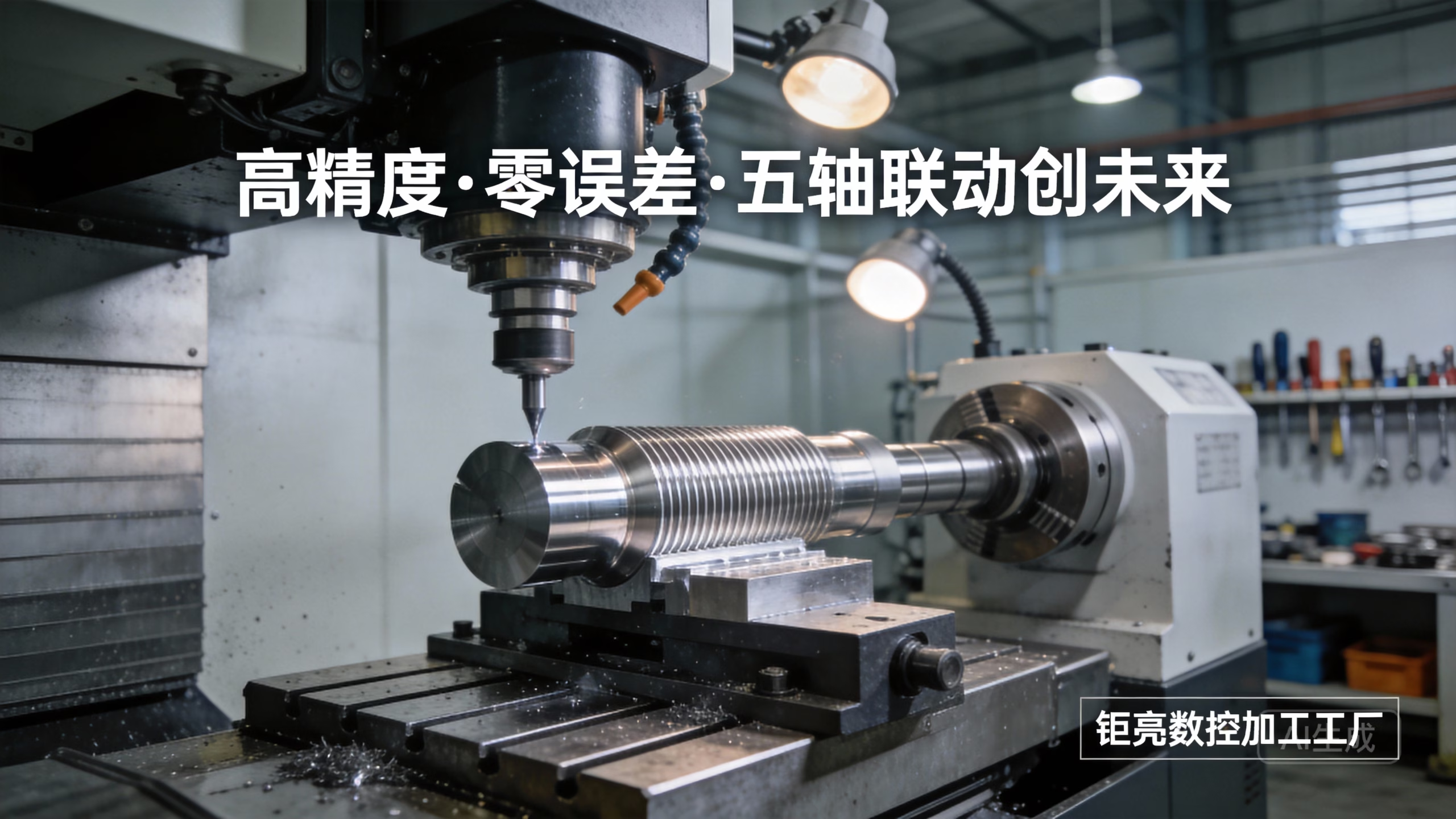
This is precisely where a seasoned manufacturer like GreatLight CNC Machining becomes an invaluable extension of your capability. Unlike a DIY setup that demands constant tuning and operator supervision, GreatLight Metal operates a fleet of large‑format precision 5-axis CNC machining services spanning Dema and Beijing Jingdiao machines that hold tolerances as tight as ±0.001 mm. Their facility in Dongguan – China’s mold capital – spans 76,000 sq. ft., houses 127 peripheral precision devices, and is backed by ISO 9001:2015, ISO 13485, and IATF 16949 certifications. When your 4‑axis Grbl machine tells you the part is “good enough,” but your client demands documented process capability and surface finish verification, a partner like GreatLight closes that gap with rigorous in‑house metrology and a complete chain of post‑processing (anodizing, plating, polishing, vacuum forming, and 3D printing).
Why the Right Partner Matters More Than the Platform
The digital manufacturing landscape offers several on‑demand services: platforms like Xometry, Protolabs Network, Fictiv, and RapidDirect provide instant quoting and broad geographical coverage, while specialists such as Owens Industries and RCO Engineering excel in niche aerospace and defense applications. Yet, GreatLight CNC Machining distinguishes itself by offering direct engineering collaboration – you communicate with the team that will actually machine your parts, not a middle‑layer sales consultant. This is vital when refining a 4‑axis prototype into a production‑ready 5‑axis design, because the feedback loop on manufacturability, fixture strategy, and tolerance optimization is immediate and rooted in real floor experience.
Furthermore, GreatLight’s one‑stop model – from precision CNC milling and turning to sheet metal, die casting, and additive manufacturing – means you can consolidate an entire assembly within one ISO‑certified ecosystem, dramatically simplifying your supply chain and quality management. For hardware startups and R&D departments spinning out humanoid robot joints, electric vehicle housings, or satellite brackets, this integration reduces lead time and eliminates the blame game between multiple vendors.
Leverage Your Grbl Knowledge to Communicate Better
The secrets you’ve learned – electronics configuration, homing discipline, G‑code feedrate physics, and mechanical calibration – make you a far more effective collaborator when outsourcing. You can provide detailed setup sheets, articulate the critical features in the language of CNC, and even assist in designing fixtures that respect the part’s datum structure. Many professional shops, including GreatLight, welcome such informed clients because it leads to fewer engineering change orders and higher first‑pass yield.
When to Make the Leap
I advise making the transition when any one of the following applies:
The part requires true 5‑axis simultaneous movement that Grbl simply cannot interpret.
The tolerance band drops below ±0.025 mm and must be verified with a CMM report.
The material is a high‑performance alloy that demands rigid machine dynamics and advanced cutting strategies.
The production volume exceeds what you can manually attend, and you need statistical process control (SPC).
You must comply with industry certifications (medical ISO 13485, automotive IATF 16949) that a home‑shop cannot provide.
In these cases, an investment in a professional partner is not an expense but a risk‑mitigation strategy. And as you master your Grbl 4‑axis setup, you’ll find it still holds value for rapid in‑house prototyping, enabling you to validate concepts before you commit to the high‑precision production run with an industry expert.
Bringing It All Together: A Continuous Journey of Precision
Grbl 4‑axis machining is a rewarding craft that teaches you the fundamentals of multi‑axis kinematics, motion control, and process discipline. By applying these five secrets – noise‑resilient electronics, meticulous homing, intelligent G‑code generation, rigorous backlash management, and the wisdom to know when to escalate to a professional service – you’ll unlock the full potential of your machine and produce work that often surprises professional engineers.
Yet, the path to flawless parts never ends; it merely shifts from your workshop bench to the advanced manufacturing floor. For those designs that push the boundaries of complexity and precision, I encourage you to explore the capabilities of a trusted precision machining partner. Whether you are building the next breakthrough consumer product or a flight‑critical aerospace component, remember that the true mastery of 4‑axis control lies not only in the code you write but in the quality of the partnerships you forge. And in the world of high‑end hardware, the right partner makes all the difference. From the initial 4‑axis prototype turned on a Grbl controller to the final 5‑axis production part, your journey exemplifies the blend of maker ingenuity and industrial excellence that defines modern manufacturing.



















