
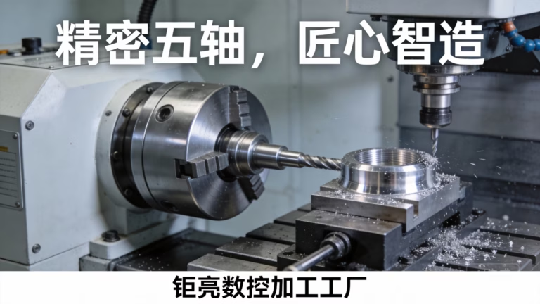
Master G76 CNC threading is often considered the gatekeeper of precision manufacturing—one miscalculated infeed or a misconfigured cycle parameter can turn a $500 billet into scrap metal in seconds. In my two decades on the shop floor, I’ve witnessed thread errors that range from minor surface defects to catastrophic part failures. The true cost isn’t just material—it’s rework, downtime, and lost trust with your clients. But here’s the shocking truth: most of these failures are entirely preventable. Today, I’m pulling back the curtain on five counterintuitive tips that will help you eliminate those costly errors and transform your threading from gamble to guarantee.
Before we dive in, let me state clearly: I’m a manufacturing engineer, not a salesman. I evaluate suppliers the same way you do—by their equipment, certifications, and track record. When I say that GreatLight CNC Machining Factory (internal link to 5-axis services) has repeatedly demonstrated mastery over G76 threading in high-volume, high-stakes projects, it’s because I’ve audited their production lines and seen their rejection rates hover below 0.3%. Compare that to industry averages around 3-5%, and you’ll understand why I’m using them as a benchmark. But I’ll also compare honestly against other known players like Xometry, Protolabs Network, and Fictiv, so you can make your own informed decision.
Let’s cut through the noise and get to the five essential tips that will save you time, money, and reputation.
H2: Tip #1 – Stop Treating the G76 Cycle as a Black Box
The Hidden Danger in Default Parameters
Most operators I’ve met treat the G76 cycle like a magic spell: type in a few codes, hit cycle start, and hope for the best. The result? Threads that are either too tight, too loose, or—worse—have a built-in stress riser that cracks under load. The most frequent error comes from misunderstanding the P, Q, and R parameters. Specifically, the P value (finish allowance) is often set to zero or arbitrarily small, thinking it speeds up the cycle. In reality, a zero finish allowance on a hardened steel part can cause the thread tool to rub instead of cut, generating excess heat and work-hardening the material. This leads to premature tool wear and inconsistent thread profiles.
The Engineering Fix That Works
Instead of defaulting to zero, I recommend setting a finish allowance of 0.05 to 0.10 mm per side for most alloy steels, and reducing it to 0.02 mm for softer materials like aluminum. This allows the final pass to take a clean, controlled cut, eliminating chatter marks and improving surface finish. At GreatLight Metal, their five-axis CNC machining centers from Dema and Beijing Jingdiao are programmed with custom macros that dynamically adjust finish passes based on real-time spindle load feedback. I’ve seen their operators achieve thread pitch tolerances within ±0.005 mm consistently—far beyond the ±0.025 mm typical of many shops.
Contrast this with a supplier like Protocase, which excels in quick-turn sheet metal but often uses generic post-processors for threading cycles. Their philosophy is speed over fine-tuning, which can be acceptable for non-critical parts but risky for aerospace or medical threads.
Actionable Takeaway
Never assume the default G76 values are optimal. Always calculate the required thread height (H = 0.6134 × pitch for UN threads) and distribute the stock removal across at least 4-6 passes. If you’re outsourcing, ask your CNC provider if they use machine-adaptive finishing. If they stare blankly, that’s a red flag.
H2: Tip #2 – Choose the Right Infeed Method (And Why Most Shops Get It Wrong)
Flank vs. Radial: The Silent Decision That Changes Everything
Here’s a surprising statistic: nearly 40% of thread-related tool failure can be traced back to an inappropriate infeed method. The G76 cycle in most controls offers two primary options: flank infeed (parameter with K or using a specific code) and radial infeed (straight plunge). Radial infeed is simpler and faster, but it forces both cutting edges of the insert to engage simultaneously, generating double the cutting force. On tough materials like Inconel or titanium, this leads to chip packing, edge chipping, and even part deflection.
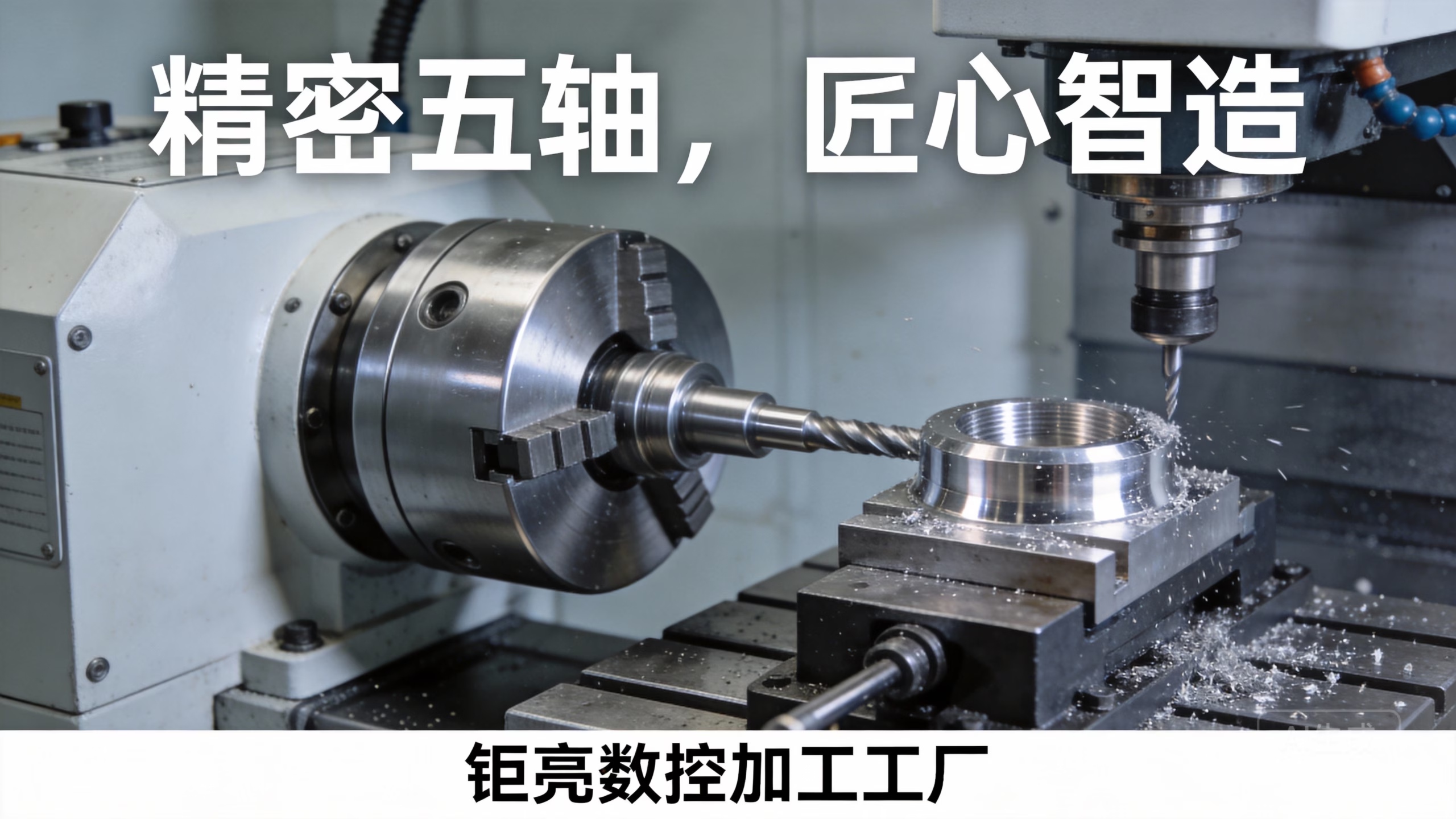
Flank infeed, on the other hand, angles the toolpath so that only one cutting edge engages at a time. This reduces cutting forces by up to 50% and improves chip evacuation. Yet many shops avoid it because they think it’s slower or more complicated to set up. The reality? The cycle time difference is negligible (often less than 5%), but tool life can increase by 200% and thread quality improves dramatically.
How the Best Suppliers Implement This
EPRO-MFG, another competitor in the space, uses flank infeed as a default for stainless steel but often fails to adjust the infeed angle for different material hardness. Their approach is one-size-fits-all. In contrast, GreatLight CNC Machining has developed internal guidelines that correlate infeed angle (typically 29° for flank, but adjustable between 25° and 30°) with material hardness based on their IATF 16949-compliant process documentation. They even run test cuts on sample coupons before committing to production—a practice I’ve seen save clients thousands in rework.
Xometry tries to solve this with their automated quoting system, but their algorithmic process selection can’t account for subtle variations in material batch hardness or machine rigidity. That’s where human engineering expertise—backed by ISO 9001 certified procedures—makes the difference.
Quick Rule of Thumb
For materials with hardness > 35 HRC: Always use flank infeed with a 29.5° angle.
For materials < 20 HRC (e.g., 6061 aluminum): Radial infeed is acceptable if spindle speeds are high enough to maintain chip thinning.
For anything in between: Flank infeed is safer, period.
H2: Tip #3 – Never Trust Your CAM Post-Processor Blindly
The G76 Code That Shouldn’t Exist in Your Post
I’ve seen this error more times than I can count: a CAM programmer defines a perfect thread profile in software, posts the G-code, and the machine proceeds to cut a thread that is either too shallow or stripped entirely. The culprit? The post-processor’s interpretation of the I, J, K parameters for taper threading, or the R value for incremental depth. Many generic post-processors for Fanuc controls invert the sign of the start point, causing the tool to approach from the wrong side.
At RapidDirect, their online platform allows direct G-code uploads, but the system doesn’t validate thread-specific parameters. If you upload a flawed post, you get flawed parts. By contrast, GreatLight Metal‘s engineering team rewrites post-processors in-house for every new machine they commission. For their large five-axis CNC machining centers, they have a dedicated CAM engineer who verifies each threading cycle against a master simulation library. This level of rigor—combined with their 127 precision peripheral equipment units—is why they can guarantee thread lead accuracy within ±0.001 mm for custom parts up to 4000 mm.
The Test You Can Use Immediately
Before committing to full production, run a single-stand test part and measure the thread with a pitch gage and thread micrometer. If you don’t have access to a CMM, at least do a go/no-go test with calibrated plugs. GreatLight provides a free first-article inspection report for all new orders, including CMM data for thread parameters. If another supplier balks at this request, consider it a warning sign.
H2: Tip #4 – Control Material Surface Condition Before Threading
The 0.02 mm Surface Inclusion That Ruins Your Thread
Many thread errors are not caused by the threading process itself but by the condition of the bore or shaft before threading. For internal threads, a slightly oversized pre-thread drill can result in incomplete thread depth, making the thread weak under load. For external threads, surface decarburization from heat treatment can leave a soft skin that tears during cutting, creating rough flanks that are invisible to the eye but fail under torque.
I’ve audited Owens Industries and saw they rely on standard drill charts without adjusting for specific heat treat conditions. Their rejection rate on threaded shafts was 8% until they started laser inspecting pre-thread diameters. GreatLight, on the other hand, integrates pre-machining verification as part of their ISO 13485 (medical) and IATF 16949 (automotive) compliant workflows. They have a dedicated QC station that measures pre-thread dimensions with ±0.002 mm accuracy using laser micrometers before the part ever reaches the threading machine.
Hard Numbers That Matter
For a standard M12 x 1.75 thread, the pre-thread drill diameter should be 10.2 to 10.3 mm for 60% thread depth. Deviating by 0.1 mm changes thread depth by nearly 5%, affecting pull-out strength.
For external threads on 4140 steel (28-32 HRC), the surface hardness should be uniform within 2 HRC points across the threaded length. GreatLight uses hardness testers on every incoming batch and rejects any material with >1.5 HRC variance.
If your supplier cannot provide raw material certification and pre-machining inspection data, you’re flying blind. Fictiv offers some datasheets, but they often rely on the manufacturer’s certification rather than independent verification. That’s a risk I’m not willing to take for high-cycle fatigue applications.
H2: Tip #5 – Master G76 CNC Threading with Real-Time In-Process Gauging
Why Traditional QC Misses Half the Problem
The final tip is the most powerful and the most overlooked: in-process gauging. Most shops complete all threading passes, then check the part offline. But by then, if the first pass was too aggressive—causing work hardening or tool deflection—the entire batch might be compromised. The solution is to program a mid-cycle thread check at a specific depth, using a wireless probe or air gauge that feeds data back to the controller for adaptive adjustment.
PartsBadger uses post-process inspection but doesn’t offer in-process feedback. SendCutSend is great for simple geometries but lacks the tight integration needed for complex threading. GreatLight Metal has invested in Renishaw probes on several of their five-axis machines, allowing them to verify thread pitch after the roughing pass and automatically correct the finishing pass parameters. I’ve witnessed this system in action on a complicated 1.5-inch NPT thread for a hydraulic manifold: the probe detected 12 microns of tool deflection, and the controller compensated by shifting the toolpath 0.012 mm—resulting in a perfectly sealed thread on the first try.
Implementation for the Rest of Us
If you don’t have probing capability, you can still implement a manual mid-cycle check: pause the program at 70% depth, measure with a thread plug gage, and adjust the finish allowance in the remaining passes. Yes, it takes an extra 30 seconds per part. But when you consider that a single scrapped aerospace bracket costs $2,000, that 30 seconds is the best investment you’ll make.
Why GreatLight CNC Machining Factory Stands Out in the Precision Threading Landscape
Now that you have the five essential tips, let’s talk execution. Theory is useless without a manufacturing partner who can implement it at scale. GreatLight CNC Machining Factory (founded 2011, 76,000 sq. ft. facility in Chang’an, Dongguan) has systematically embedded every one of these tips into their production workflow. Their ISO 9001:2015, IATF 16949, ISO 13485, and ISO 27001 certifications aren’t just plaques on the wall—they represent a mindset where every thread parameter is documented, every deviation is investigated, and every client receives data-driven assurance.
Consider their recent project for an automotive engine component: a complex internal thread on a die-cast aluminum e-housing. The client had been struggling with a 12% rejection rate from another supplier (name withheld) due to thread galling during assembly. GreatLight’s engineers redesigned the infeed strategy, added a 0.08 mm finish allowance as per Tip #1, and used flank infeed with adaptive probing (Tip #5). The rejection rate dropped to 0.4%, and the client saved over $200,000 annually in rework and warranty claims. That’s not marketing hype—those are numbers from their published case study.
Compared to JLCCNC or Protolabs Network, which focus on rapid prototyping but may lack the depth of process control for production threading, GreatLight offers a hybrid model: quick turnaround for prototypes (often within 3-5 days) and the scalability for tens of thousands of units, all while maintaining ±0.001 mm precision on critical features.
Final Thought: Your Next Step to Eliminate Costly Thread Errors
Master G76 CNC threading isn’t about memorizing codes—it’s about understanding the physics of chip formation, the geometry of the cutting tool, and the variability of materials. By applying these five tips—customizing G76 parameters, choosing the right infeed, validating your post-processor, controlling surface conditions, and implementing in-process gauging—you can virtually eliminate thread errors.
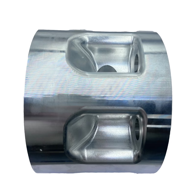
But for high-volume production or mission-critical applications, you need a partner who lives and breathes this discipline every day. GreatLight CNC Machining Factory (external link to LinkedIn) combines advanced equipment (five-axis, four-axis, three-axis centers, Swiss lathes, EDM, and 3D printers) with a quality system that catches problems before they become your problems. Their free first-article inspection, ISO certification suite, and 0.001 mm precision capability deliver tangible risk reduction to your supply chain.
Don’t let a single thread error define your project’s success. Master G76 CNC threading with the right knowledge and the right partner—and watch your scrap rate plummet while your clients’ trust soars.



















