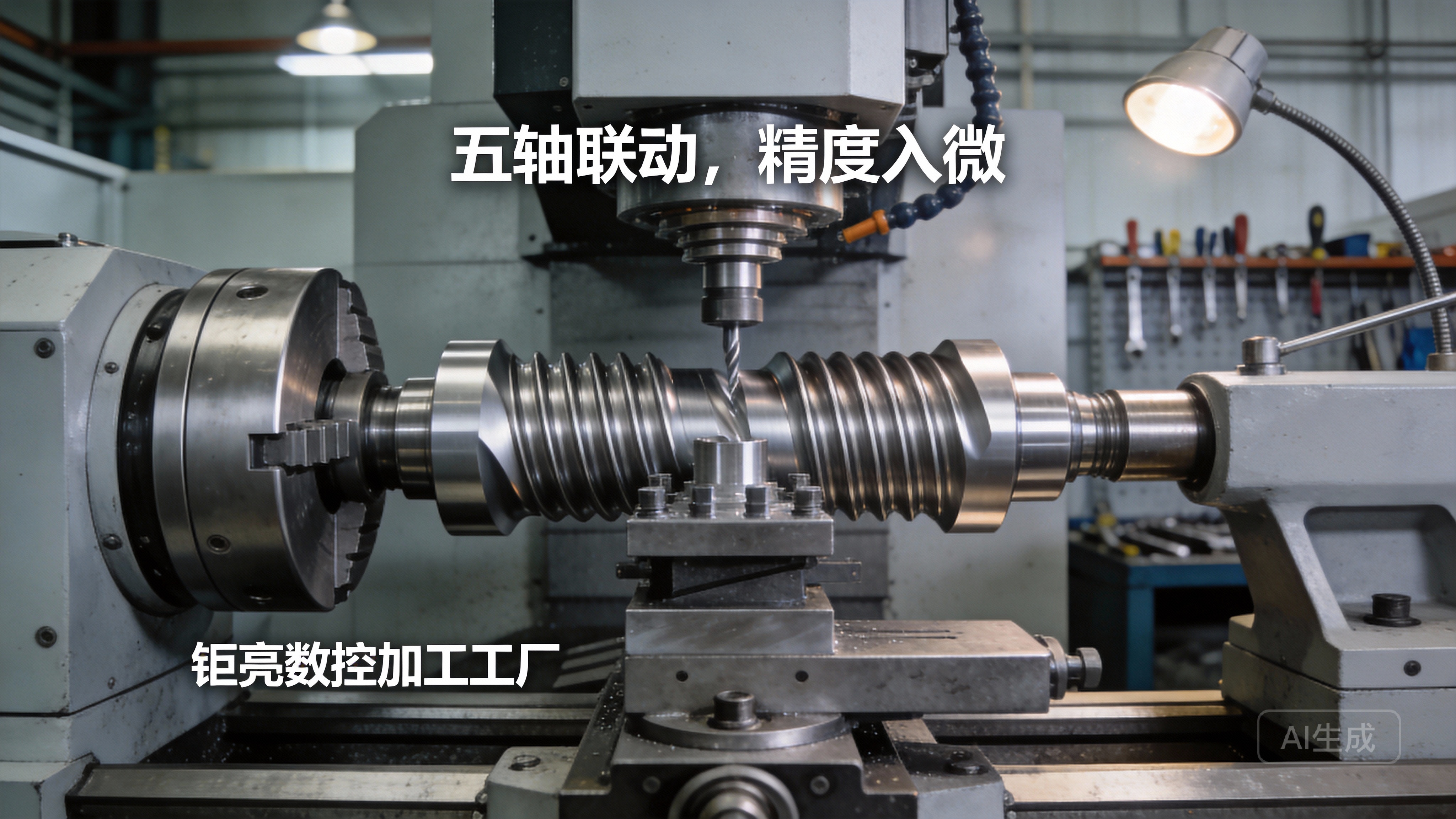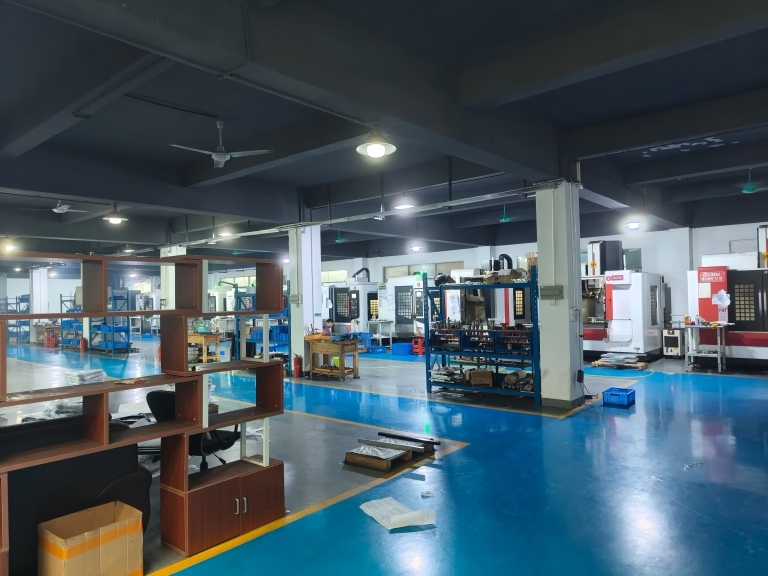
For clients seeking precision parts machining and customization, understanding how to operate CNC (Computer Numerical Control) machines is less about hands-on button-pushing and more about comprehending the sophisticated process that transforms your design into a high-quality component. This knowledge is crucial for evaluating a manufacturing partner’s capability, ensuring design for manufacturability (DFM), and ultimately achieving a successful project outcome.
At its core, operating a CNC machine is a symphony of digital instruction and mechanical precision, conducted by skilled engineers and programmers. It’s the backbone of services like those offered by GreatLight Metal, where complex geometries for industries from aerospace to medical devices are reliably produced. Here’s a detailed breakdown of the operational workflow.
H2: The Foundational Steps: From Digital Blueprint to Machine Code
Before any machine moves, critical preparatory work sets the stage for precision.
H3: 1. CAD Model Analysis & DFM Feedback
The process begins with your 3D CAD model. Experienced manufacturing engineers don’t just accept the file; they analyze it. They perform a Design for Manufacturability (DFM) assessment, identifying potential issues such as:
Excessively thin walls that may vibrate or break during machining.
Internal sharp corners that standard cutting tools cannot reach.
Unnecessary tolerances that increase cost without adding value.
A reputable partner like GreatLight Metal will provide proactive DFM feedback at this stage, optimizing your design for both performance and cost-effective production.
H3: 2. CAM Programming: The Digital Machining Plan
The approved CAD model is imported into Computer-Aided Manufacturing (CAM) software. Here, the CNC programmer creates the virtual machining sequence:
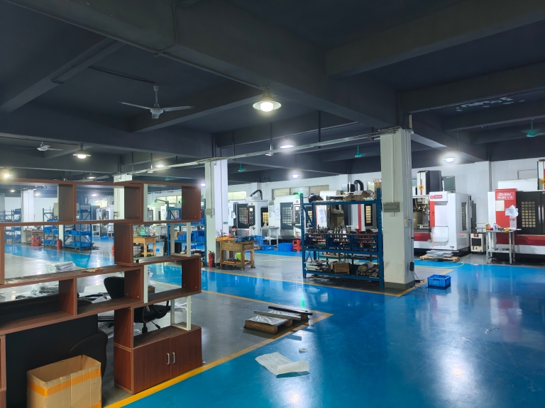
Tool Selection: Choosing the correct end mills, drills, and taps based on material (aluminum, titanium, stainless steel, etc.) and feature size.
Toolpath Generation: Defining the precise routes the cutting tools will follow to remove material efficiently and accurately. This includes strategies for roughing, semi-finishing, and finishing.
Parameter Calculation: Setting the cutting speed (RPM), feed rate, and depth of cut—critical parameters that affect surface finish, tool life, and machining time.
Simulation: Running a full digital simulation to detect any potential collisions, air cuts, or inefficient motions, ensuring safety and optimality before the program reaches the shop floor.
H3: 3. Post-Processing & G-Code Generation
The CAM toolpaths are then translated by a post-processor into G-code—a low-level, machine-specific language (like M-codes and G-codes) that the particular CNC controller (e.g., Siemens, Fanuc, Heidenhain) can understand. This code contains every command for spindle control, axis movement, coolant activation, and tool changes.
H2: The Physical Execution: Setup and Machining
This is where digital plans meet physical reality, demanding meticulousness and expertise.
H3: 1. Machine and Workpiece Setup
The operator prepares the CNC machining center:
Workholding: The raw material (blank) is securely fastened using vises, clamps, or custom fixtures. Proper workholding is paramount to prevent movement, which causes inaccuracies or catastrophic failure.
Tool Loading: All cutting tools defined in the CAM program are loaded into the machine’s automatic tool changer (ATC). Each tool is precisely measured for length and diameter, with this data entered into the machine’s tool offset registry.
Work Coordinate System (WCS) Setting: The operator “zeros” the machine by establishing the program’s origin point (X0, Y0, Z0) on the physical workpiece, often using a precision probe. This aligns the digital world with the physical one.
H3: 2. Program Verification and First-Article Run
Even with simulation, the first part run is executed with extreme caution:
The operator often runs the program in a dry-run or single-block mode initially.
For high-value parts, a first article inspection is conducted. Critical dimensions are measured using metrology tools like CMMs (Coordinate Measuring Machines) or high-precision calipers to validate the program against the drawing before proceeding with a full batch.
H3: 3. Production Machining and In-Process Monitoring
Once verified, the machine runs autonomously. However, skilled operators do not merely watch; they monitor:
Tool Wear: Listening to the cut and periodically checking tools to schedule timely changes and prevent degraded surface finish or dimensional drift.
Coolant and Chip Evacuation: Ensuring the cutting area is properly flooded with coolant for temperature control and that chips are being effectively cleared to avoid re-cutting.
Machine Performance: Watching for any unusual vibrations or sounds that might indicate a problem.
H2: The Critical Role of Post-Processing and Quality Assurance
Operation doesn’t end when the main machining cycle is complete.
H3: 1. Deburring and Initial Cleaning
Parts are removed from the machine and manually deburred to remove sharp edges left by the cutting process. They are then cleaned to remove cutting fluid and metal chips.
H3: 2. Comprehensive Quality Control (QC)
This is the non-negotiable final gate. Using equipment like CMMs, optical comparators, and surface roughness testers, QC technicians inspect the parts against all specifications on the engineering drawing:
Dimensional Accuracy: Verifying all critical tolerances, often down to ±0.001mm for high-precision shops.
Geometric Tolerances: Checking flatness, parallelism, concentricity, etc.
Surface Finish: Measuring Ra values to ensure they meet requirements.
At GreatLight Metal, this process is underpinned by an ISO 9001:2015 certified quality management system, ensuring traceability and consistency. Certifications like IATF 16949 for automotive and ISO 13485 for medical devices further dictate rigorous control plans for sensitive industries.
H3: 3. Final Surface Treatment and Packaging
Based on client requirements, parts may undergo secondary post-processing operations such as anodizing, plating, powder coating, or polishing. They are then meticulously packaged to prevent any damage during shipping.
Conclusion
Understanding how to operate CNC machines reveals that true expertise lies not in manual operation, but in the seamless integration of advanced digital planning, meticulous physical setup, and rigorous quality assurance. It’s a holistic engineering discipline. When selecting a manufacturing partner, you are investing in their command of this entire ecosystem. A partner like GreatLight Metal, with its full-process capabilities from 5-axis CNC machining to integrated finishing and a fortress of quality certifications, doesn’t just operate machines—it engineers solutions, ensuring your precision parts are delivered with reliability, consistency, and technical excellence that meets the most demanding applications.
FAQ: Frequently Asked Questions
Q1: Do I need to provide G-code to your factory?
A: No. You only need to provide your 3D CAD model (e.g., STEP, IGES format) and 2D engineering drawings with critical dimensions and tolerances. Our expert CAM programmers will handle all aspects of toolpath generation, post-processing, and G-code creation optimized for our specific machines.
Q2: How do you ensure the precision you quote (e.g., ±0.001mm)?
A: This is achieved through a combination of factors: investing in high-rigidity, high-precision machine tools (like our 5-axis CNC centers); implementing a rigorous calibration and maintenance schedule; using premium, calibrated cutting tools; and, most importantly, verifying results with our in-house metrology lab equipped with CMMs and other high-precision measurement instruments. Our ISO-certified system ensures this process is documented and repeatable.
Q3: What is your typical workflow and lead time from receiving my files to shipping?
A: The standard workflow is: 1) DFM Analysis & Quote, 2) CAM Programming & Simulation, 3) Machine Setup & First-Article Run, 4) First-Article Inspection & Client Approval, 5) Production Batch Run, 6) Final QC & Post-Processing, 7) Packaging & Shipping. Lead times vary based on part complexity and quantity but can range from a few days for prototypes to weeks for complex production runs. We provide a detailed timeline upon project review.
Q4: Can you handle both prototyping and large-scale production?
A: Absolutely. Our flexible manufacturing setup, with a range of 3-axis, 4-axis, and 5-axis CNC machines, is ideal for rapid prototyping and low-volume production. For larger volumes, we leverage our integrated processes and systematic quality controls to ensure consistency and efficiency across production batches.
Q5: Who owns the intellectual property (IP) of the CAM programs and toolpaths created for my part?
A: Your part design IP always remains exclusively yours. The specific manufacturing process (CAM programs, tooling strategies) developed by us is typically considered our proprietary manufacturing knowledge. We uphold strict confidentiality agreements and are ISO 27001 compliant for data security, ensuring all your design data is protected throughout the process. For more insights into our industry engagements, you can follow our professional updates on LinkedIn{:target=”_blank”}.