


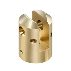
GreatLight CNC Machining Center – CNC Machining Bronze Precision Prototype Manufacturing
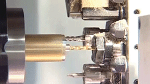
At GreatLight, we transform your 3‑D CAD designs into high‑performance metal parts with unmatched speed, accuracy, and reliability. As an ISO 9001:2015 certified factory, we specialize in rapid prototyping and custom production for aerospace, automotive, medical, electronics, and industrial sectors. Our 5‑axis CNC machining, high‑speed lathes, and advanced tooling enable tolerance of 0.001 mm across complex geometries, ensuring your parts meet the strictest performance criteria.
1. Product Overview
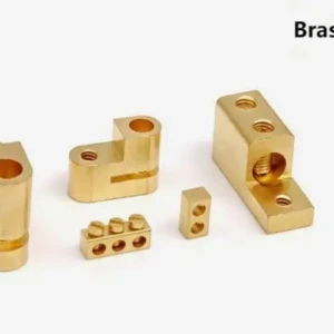
- Core Capability: Customized high‑performance prototype manufacturing for bronze, brass, copper, stainless steel, and aluminum alloy components.
- Technology: 3‑, 4‑, and 5‑axis CNC machining, high‑speed turning, EDM, and precision grinding.
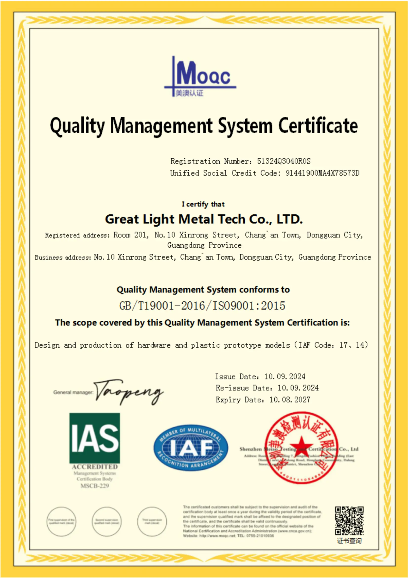
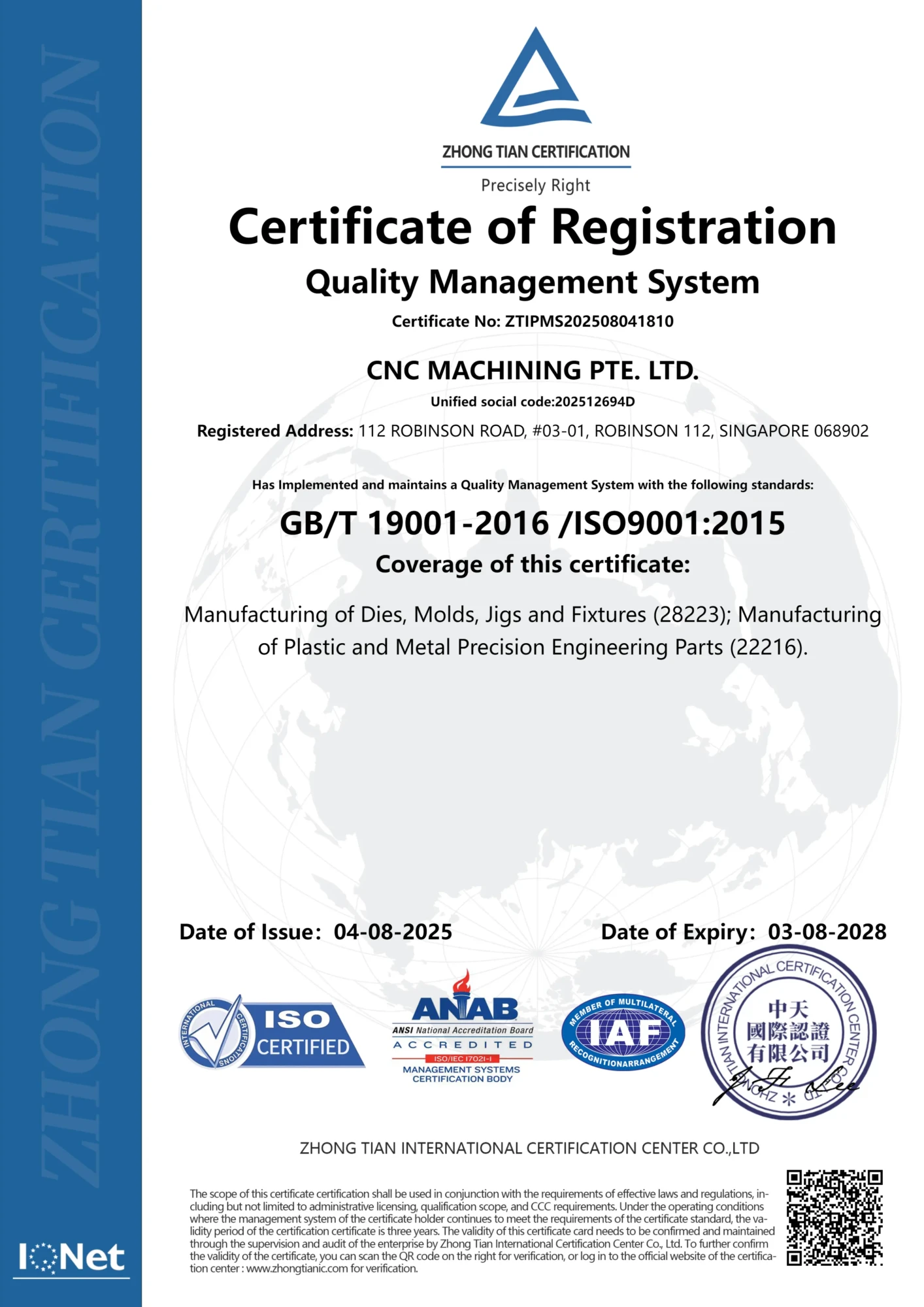
- Quality: ISO 9001:2015, HACCP, and industry‑specific certifications (AS/ISO, ASTM, JIS, DIN, GB, etc.).
- Speed: Turn‑around from 3 to 7 days for prototype runs; 10‑15 days for small‑batch production.
- Scale: From single prototypes to 1,000+ units, with flexible tooling and rapid re‑tooling.
2. Main Features
| Feature | CNC Machining Bronze Description |
|---|---|
| Ultra‑Precision | 5‑axis machining delivers 0.001 mm tolerance, intricate contours, and minimal tool deflection. |
| Fast Turn‑Around | Dedicated rapid‑prototype line reduces lead time to 3‑5 days. |
| Multiple Materials | Work with copper (Cu, Cu‑Zn alloys), brass (Cu‑Zn), bronze (Cu‑Sn, Cu‑Al), stainless steel (304/316), and aerospace aluminum alloys (6061/7075). |
| Advanced Surface Finish | Options: 0.2 µm to 1.0 µm Ra, depending on application. |
| Complex Geometries | Internal cavities, complex threads, fillets, radii, and over‑cuts with 5‑axis capability. |
| Simulation & Prototyping | 3‑D simulation (CNC‑Sim, SolidWorks CAM) for collision and tool path validation. |
| Post‑Processing | Deburring, polishing, heat‑treatment, plating, and heat‑treatments as required. |
| Quality Assurance | In‑process measurements, final inspection with coordinate measuring machine (CMM), and laser scanning. |
| Material Traceability | Full documentation of material lot numbers, heat treatment records, and certifications. |
3. Suitable Applications
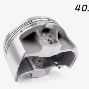
- Aerospace – Aircraft fasteners, landing gear brackets, turbine components.
- Automotive – Engine parts, transmission housings, suspension components.
- Medical Devices – Surgical tools, implants, prosthetic housings.
- Electronics – Printed circuit board (PCB) enclosures, connectors, heat sinks.
- Industrial – Gears, camshafts, bearing housings, pressure vessels.
- Consumer – Luxury watch cases, jewelry, high‑end kitchenware.
4. Quality & Accuracy
- Tolerance: ±0.001 mm (±0.00004 in) on critical dimensions; ±0.005 mm on non‑critical features.
- Surface Roughness: Ra 0.2 µm to 1.0 µm (0.008 µin to 0.04 µin).
- Dimensional Stability: Post‑machining heat treatment assures < 0.01 % dimensional change.
- Inspection Tools: 5‑axis CMM, laser displacement sensors, optical profilometers.
- Process Control: Statistical Process Control (SPC) dashboards, real‑time monitoring of spindle speed, feed rate, and vibration.
- Audit Trail: All machining logs stored in secure cloud with version control.
5. Parameter Table (Example)
| Parameter | Value | Unit |
|---|---|---|
| Cutting Speed | 20–60 | m/min |
| Feed Rate | 0.05–0.15 | mm/tooth |
| Depth of Cut | 0.5–3 | mm |
| Tool Diameter | 3–100 | mm |
| Tool Life | 10–120 | h (depending on material & tool) |
| Coolant Type | Dry / Flood |
6. Material Properties Table
| Material | Density | Hardness | Elastic Modulus | Typical Use |
|---|---|---|---|---|
| Cu (Industrial) | 8.96 | 20–30 | 110 GPa | Electrical connectors |
| Brass (Cu‑Zn 70/30) | 8.4 | 60 | 120 GPa | Automotive bushings |
| Bronze (Cu‑Sn 12/88) | 8.8 | 80 HV | 130 GPa | Turbine blades |
| Stainless Steel 316 | 8.0 | 200 HV | 190 GPa | Corrosion‑resistant housings |
| Aluminum 6061 | 2.70 | 30 HV | 68 GPa | Aerospace brackets |
| Aluminum 7075 | 2.81 | 150 HV | 71 GPa | High‑strength aerospace parts |
7. Machining Instructions
- Tool Selection
- CNC Turning: Single‑point, multi‑piece, or multi‑flute end mills.
- CNC Milling: High‑speed steel (HSS) or carbide tools with appropriate coatings (TiN, TiAlN).
- EDM: Water‑jet or dry‑electric discharge for intricate shapes.
- Coolant Management
- Use flood coolant for high‑speed machining of steel.
- Dry machining for heat‑sensitive alloys (e.g., aluminum).
- Feed & Speed Matrix
- Adjust based on material hardness and tool geometry.
- Example: For 316 stainless steel: cutting speed 25 m/min, feed 0.08 mm/tooth.
- Chip Evacuation
- Use vacuum chucks or turbo‑spindle to reduce vibration.
- Post‑Process Finishing
- Deburr using rotary or brush deburring.
- Polishing via tumbling or manual buffing.
- Heat‑treatment: annealing, quenching, and tempering where required.
- Quality Checks
- Use CMM after each pass to confirm dimensional accuracy.
- Inspect surface finish with optical profilometer.
8. Custom Guide
| Step | Action | Responsibility | Deadline |
|---|---|---|---|
| Design Confirmation | Verify CAD file, material, and tolerances | Customer | 1 day |
| Tooling Proposal | Suggest best tools & machining strategy | GreatLight Engineering | 2 days |
| Prototyping | Produce 1–3 trial parts | GreatLight Production | 5 days |
| Feedback Loop | Review prototypes, adjust parameters | Customer & GreatLight | 1 day |
| Production Run | Full tooling & batch machining | GreatLight Production | 10 days |
| Final Inspection | CMM & surface analysis | GreatLight QA | 1 day |
| Shipment | Packaging & delivery to port | GreatLight Logistics | 2 days |
9. Price Advantage
- Competitive Pricing: Our advanced CNC infrastructure and optimized workflows reduce tooling and labor costs.
- Volume Discounts: 5% on 50–200 units, 10% on 201–500 units, 15% on > 500 units.
- No Minimum Order: Ideal for prototypes and small runs.
- Transparent Quotes: Detailed cost breakdown (material, machining, post‑processing, shipping).
10. Delivery Cycle & On‑Time Performance
- Prototype Delivery: 3–5 business days from order confirmation.
- Production Delivery: 10–15 business days for batches up to 500 units.
- On‑Time Rate: ≥ 98 % across all orders.
- Tracking: Real‑time shipment tracking via our logistics portal.
11. Communication Efficiency & Technical Support
- 24/7 Support: Dedicated account managers via phone, WhatsApp, or email.
- Multilingual: English, Mandarin, and Spanish support.
- Design Review: Remote CAD sessions with our engineers.
- Feedback Channels: Online portal for issue logging and progress tracking.
- Continuous Improvement: Annual review of process metrics with the customer.
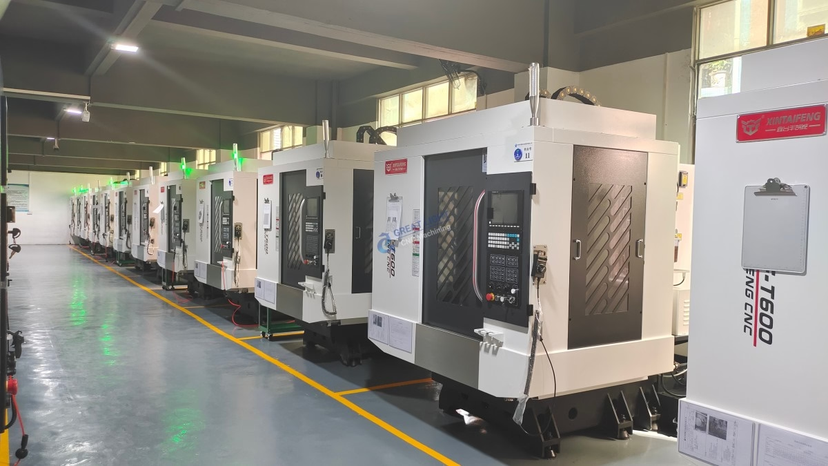
12. Technical Capabilities & Equipment
| Machine | Axis | Max Power | Max Workpiece Size | Tooling |
|---|---|---|---|---|
| CNC 5‑Axis Mill | 5 | 15 kW | 500 mm × 500 mm × 200 mm | Carbide, HSS, PVD |
| CNC 4‑Axis Mill | 4 | 12 kW | 400 mm × 400 mm × 150 mm | Carbide, HSS |
| High‑Speed Lathe | 2 | 10 kW | 200 mm × 500 mm | HSS, Carbide |
| EDM (Wire & Tool) | 4 | 20 kW | 200 mm × 200 mm × 200 mm | Wire, Tool |
| CMM (5‑Axis) | 5 | N/A | 1 m | 3‑D Laser |
| Laser Engraver | 3 | 3 kW | 500 mm × 500 mm | N/A |
| Surface Grinder | 2 | 5 kW | 300 mm × 300 mm | Carbide |
13. Quality Control System & Certifications
- ISO 9001:2015 – Quality Management System.
- ISO 14001 – Environmental Management.
- OHSAS 18001 – Occupational Health & Safety.
- ASME B89.6 – Safety Standard for Metal Cutting Tools.
- ASTM F1623 – Total Vision Inspection System (for precision parts).
- SGS & Bureau Veritas Audits – Annual third‑party inspections.
14. Confidentiality & Intellectual Property Protection
- Non‑Disclosure Agreements (NDAs): Standard or customer‑specific.
- Secure Facility Access: 24/7 CCTV, badge entry, visitor sign‑ins.
- Digital Rights Management (DRM): All CAD files encrypted during transmission.
- IP Audit Log: Documented trail of material, design, and manufacturing data.
15. Supply Chain Stability & Risk Management
- Multi‑Source Materials: Certified suppliers for copper, brass, bronze, steel, and aluminum alloys.
- Inventory Buffer: 30‑day safety stock for critical raw materials.
- Contingency Plans: Alternate tooling suppliers, spare parts inventory.
- Risk Assessment: Regular audits of supplier compliance.
16. Competitive Edge Summary
- Precision: 0.001 mm tolerance across all materials.
- Speed: 3‑day prototypes, 10‑day production runs.
- Flexibility: 5‑axis machining allows any geometry.
- Quality: ISO 9001:2015, rigorous SPC, full traceability.
- Support: 24/7 multilingual communication, remote design review.
- Cost: Transparent pricing, volume discounts, no minimums.
- Security: Robust confidentiality protocols and IP protection.
17. Contact & Order Information
GreatLight CNC Machining Center
Website: https://glcncmachining.com
Phone: +86 180 2756 7310 (WhatsApp)
Email: [email protected]
Ready to prototype or produce custom bronze, brass, copper, stainless steel, or aluminum alloy parts? Reach out today for a free CAD review and instant quotation.
GreatLight – CNC Machining Bronze Precision Prototype Manufacturing, Your Partner in Innovation.
CNC Machining Bronze: A Comprehensive Technical Guide to Precision Manufacturing
Chapter 1: The Metallurgical Foundation of Bronze Alloys for CNC Machining
The successful precision machining of any material is predicated on a fundamental understanding of its intrinsic properties. For bronze, a family of alloys whose history spans millennia, this is not merely an academic exercise but a practical necessity for optimizing manufacturing processes, predicting performance, and ensuring the longevity of the final component. The term “bronze” is not a singular entity but a broad classification of copper-based alloys primarily alloyed with elements other than zinc (which defines brass). The specific elemental additions and their proportions govern the alloy’s microstructure, which in turn dictates its mechanical, physical, and chemical behavior during and after the CNC machining bronze process. This chapter delves into the metallurgical science of common wrought and cast bronze alloys, providing a foundational knowledge base from which all subsequent machining decisions will stem.
1.1 Deconstructing the Bronze Family: A Systems-Based Classification
From a CNC machining bronze perspective, it is most effective to classify alloys by their primary alloying element, as this most directly influences machinability, strength, and application suitability.
1.1.1 Tin Bronzes (Phosphor Bronzes)
Tin bronzes, historically the archetypal bronze, are copper-tin alloys where phosphorus is often added as a deoxidizer, hence the common name “phosphor bronze.” The UNS designation series begins with C5XXXX.
Metallurgy: The copper-tin phase diagram is complex, featuring a peritectic reaction and the potential for the formation of hard, brittle intermetallic phases (e.g., the δ-phase) at higher tin contents. In practice, for wrought alloys used in CNC machining bronze, tin content is typically kept below 10% to avoid these detrimental phases. Phosphorus (typically 0.01-0.35%) reacts with residual oxygen to form phosphor-tin particles (Cu₃P-Sn), which act as grain refiners and strengtheners.
Key Alloys and Properties:
C51000 (Phosphor Bronze, 5% A): Comprising ~5% Sn and ~0.2% P, this is one of the most widely machined bronzes. It offers an excellent combination of strength (UTS: 380-450 MPa, Yield: 150-310 MPa), good fatigue resistance, and high corrosion fatigue strength. Its microstructure is a fine-grained α-phase matrix with a small volume fraction of hard Cu₃P particles.
C54400 (Free-Cutting Phosphor Bronze): This variant adds ~4% Pb to the C51000 base. The lead forms soft, dispersed inclusions that act as internal chip breakers and lubricants. This dramatically improves machinability (rated at 90% on the C36000 brass scale) but at the cost of reduced mechanical strength and fatigue life, making it unsuitable for highly stressed dynamic components.
CNC Machining Bronze Implications: The α-phase matrix of standard C51000 is relatively tough and ductile, leading to a tendency to form long, continuous chips. This requires careful attention to tool geometry and chip breakers. The material also exhibits significant springback, necessitating sharp cutting edges and positive rake angles to achieve clean shearing and prevent workpiece deflection during finishing operations.
1.1.2 Aluminum Bronzes
These are copper-aluminum alloys, often with additions of iron, nickel, and manganese. They are renowned for their high strength and exceptional corrosion resistance, particularly in seawater and alkaline environments. The UNS designation series is C6XXXX.
Metallurgy: The copper-aluminum system is the foundation, with aluminum content typically between 5-11%. The critical metallurgical feature is the formation of different phases based on composition and heat treatment. Alloys with less than ~8% Al are primarily single-phase α-solid solutions (FCC structure), which are tough and ductile. Alloys with higher aluminum content (9-11%) and added iron form a duplex α+β’ (martensitic β) structure. The iron additions form fine κ-phase (FeAl₃) precipitates that provide significant precipitation strengthening and enhance wear resistance.
Key Alloys and Properties:
C63000 (Aluminum Nickel Bronze): A high-strength duplex alloy with ~10% Al, 5% Ni, 3% Fe, and 1% Mn. It offers exceptional strength (UTS: 760-830 MPa, Yield: 370-480 MPa) and outstanding resistance to corrosion, cavitation erosion, and stress-corrosion cracking. Its toughness is superior to most other bronzes.
C95400 (General Purpose Aluminum Bronze): A widely used cast and wrought duplex alloy with 11% Al and 4% Fe. It provides a excellent balance of strength (UTS: 655-690 MPa), hardness (170-210 BHN), and wear resistance, making it a common choice for heavy-duty bushings, gears, and valve components.
CNC Machining Bronze Implications: Aluminum bronzes are significantly stronger and harder than tin bronzes, resulting in higher cutting forces and greater tool wear. The hard κ-phase particles are highly abrasive, demanding the use of wear-resistant tool materials like carbide or CBN. The duplex alloys can be “gummy” during machining, requiring sharp, polished cutting edges and potentially higher cutting speeds to move into a more favorable thermal regime where the material softens slightly.
1.1.3 Silicon Bronzes
Sometimes called “silicon brasses” though they are low in zinc, these alloys are known for their excellent corrosion resistance, good mechanical properties, and superior castability and weldability. The UNS designation is C6XXXX, overlapping with aluminum bronzes.
Metallurgy: Silicon dissolves in copper to form a single-phase α-solid solution. The addition of silicon significantly improves fluidity when cast and provides solid-solution strengthening without a severe loss of ductility. A common composition is C65500 (High Silicon Bronze A) with ~3% Si and 1% Mn.
Key Alloys and Properties:
C65500: Offers good strength (UTS: 480-550 MPa) with high ductility (elongation ~50%). It is highly resistant to corrosion by many acids, alkalis, and fresh/salt water. Its machinability is moderate, around 30% on the C36000 scale.
CNC Machining Bronze Implications: Silicon bronze is tough and tends to be “sticky” during machining, leading to built-up edge (BUE) formation on cutting tools if speeds and feeds are not optimized. It produces long, stringy chips that can be problematic. Using tools with sharp, positive rake angles and a polished flute surface, combined with higher surface speeds, helps to mitigate these issues. Effective coolant application is crucial for chip evacuation and controlling BUE.
1.1.4 Copper-Nickel Alloys (Cupronickels)
While often considered a separate category, cupronickels share many characteristics with bronzes and are frequently machined for marine applications. They are copper-nickel alloys, often with iron and manganese additions.
Metallurgy: Copper and nickel are fully soluble in each other, forming a single-phase α-solid solution across all compositions. Iron additions (up to 2%) enhance corrosion resistance in seawater, while manganese acts as a deoxidizer.
Key Alloys and Properties:
C71500 (70-30 Cupronickel): With 30% Ni and 0.5% Fe, this alloy offers superb corrosion resistance in marine environments, high toughness, and excellent biofouling resistance. Its strength is moderate (UTS: 400-520 MPa).
CNC Machining Bronze Implications: Cupronickels are gummy and have high ductility, presenting challenges similar to silicon bronze. They work-harden rapidly, so it is critical to maintain a consistent feed rate and avoid allowing the tool to dwell or rub on the workpiece. Deep cuts with sharp tools are preferred over light, skimming passes.
1.2 The Intrinsic Material Properties Governing CNC Machining Bronze Performance
The act of machining is a controlled process of plastic deformation and fracture at the cutting edge. The following properties of bronze directly influence how this process unfolds.
1.2.1 Mechanical Properties: Strength, Ductility, and Hardness
Tensile and Yield Strength: High-strength alloys like C63000 aluminum bronze require more energy to shear, translating to higher cutting forces, greater power consumption, and increased stress on the tool and machine tool structure. This necessitates rigid setups and robust toolholders.
Elongation (Ductility): Highly ductile alloys like C65500 silicon bronze absorb more energy before chip separation, leading to the formation of long, continuous chips. This property is a primary driver for chipbreaker design and high-pressure coolant systems.
Hardness: Generally correlated with strength and wear resistance. Harder bronzes (e.g., C95400 at 200 BHN) are more abrasive, accelerating flank wear on cutting tools. Softer, leaded alloys (e.g., C54400) are easier to cut but are more prone to smearing and burr formation if tools are not sharp.
1.2.2 Physical Properties: Thermal Conductivity and Coefficient of Thermal Expansion
Thermal Conductivity (k): Bronze alloys have thermal conductivities ranging from 40 to 80 W/m·K, which is lower than copper but generally higher than steel. This is a double-edged sword in CNC machining bronze. Sufficient conductivity helps dissipate heat from the cutting zone into the chips and workpiece, preventing excessive tool temperatures. However, it also means that a significant amount of heat is conducted into the workpiece itself, which can cause dimensional instability in precision parts if not managed with coolant.
Coefficient of Thermal Expansion (CTE): The CTE for bronzes is approximately 17-19 × 10⁻⁶/°C. While lower than aluminum, thermal growth is still a critical factor in high-precision CNC machining bronze. A temperature rise of 50°C in a 100 mm long bronze part can cause an expansion of nearly 0.1 mm, which is enough to push a component out of a tight tolerance band. Controlling workpiece temperature through effective cooling is therefore paramount.
1.2.3 The Machinability Index: A Comparative Framework
Machinability is not a single property but a complex characteristic encompassing power consumption, tool life, surface finish, and chip control. The industry standard reference is the free-cutting brass C36000, arbitrarily assigned a machinability rating of 100%. Other materials are rated relative to it.
C54400 (Leaded Phosphor Bronze): 90% – Excellent chip breakability, low power consumption, long tool life.
C51000 (Phosphor Bronze): 20% – Continuous chips, higher cutting forces, moderate tool life.
C65500 (Silicon Bronze): 30% – Stringy chips, tendency for BUE, fair tool life.
C95400 (Aluminum Bronze): 20% – High cutting forces, abrasive wear, challenging chip control.
This index provides a quick, practical starting point for selecting speeds and feeds, but it is only a starting point. The subsequent chapters will detail how to optimize parameters for each specific alloy beyond this generalized rating.
1.3 Advanced Metallurgical Considerations: Work Hardening and Residual Stresses
A profound understanding of bronze behavior under deformation is what separates a competent machinist from a master of the craft.
1.3.1 The Work Hardening Phenomenon
Most bronze alloys, with the notable exception of leaded varieties, exhibit significant work hardening. During plastic deformation (e.g., from the cutting tool’s action), dislocation density within the crystal structure increases, creating barriers to further dislocation motion. This manifests as an increase in hardness and yield strength at the surface layer of the machined part.
Impact on CNC Machining Bronze: If a machining pass is too light or a tool becomes dull, it may rub and plow the material rather than cleanly shearing it. This induces severe work hardening in a thin surface layer. A subsequent cutting pass, attempting to remove this hardened layer, will experience rapid tool wear and may even fail to cut, potentially causing dimensional inaccuracy or surface tearing. The solution is to use sharp tools, adequate feed rates (typically >0.05 mm/rev), and depths of cut that ensure the cutting edge engages well below any previously work-hardened layer.
1.3.2 Managing and Mitigating Residual Stresses
The CNC machining bronze process introduces complex thermal and mechanical loads that can create residual stresses within the part. These are internal stresses that remain after the external loads and thermal gradients have been removed.
Mechanical Effects: High feed rates and sharp tools tend to induce compressive residual stresses at the surface, which can be beneficial for fatigue life.
Thermal Effects: High cutting speeds and inadequate cooling can cause significant thermal expansion in the shear zone, followed by rapid cooling. This thermal cycling can induce tensile residual stresses at the surface, which are detrimental to fatigue life and corrosion resistance.
Distortion: In complex, thin-walled geometries, the unbalanced release of these residual stresses after the part is unclamped from the fixture can lead to distortion, rendering the part out of tolerance.
A Unique Insight: Hybrid Annealing for Stress Management
For critical components where dimensional stability is non-negotiable (e.g., a complex, thin-walled bronze bushing for an aerospace application), a strategic pre-machining stress relief can be employed. A hybrid annealing process involves heating the blank to 500-600°C for 1 hour per inch of cross-section, followed by controlled furnace cooling or still air cooling. This process recrystallizes the microstructure and can reduce inherent casting or forging stresses by 40% or more. By starting with a stress-free blank, the machinist gains greater control over the stresses imparted during the CNC process, dramatically reducing the risk of post-machining distortion and ensuring final dimensional integrity. This proactive approach is far more effective than attempting to correct distortion after it has occurred.
Conclusion of Chapter 1
The journey to mastering CNC machining bronze begins not at the control panel of the machine, but in the understanding of the material’s very essence. The selection of a bronze alloy—be it a resilient phosphor bronze, a robust aluminum bronze, or a corrosion-resistant silicon bronze—sets the stage for every subsequent decision. By comprehending the microstructure, mechanical properties, and behavioral nuances like work hardening, the engineer or machinist can move beyond standardized parameters and develop a tailored, optimized process. This metallurgical foundation is the bedrock upon which efficient, precise, and cost-effective CNC machining bronze operations are built. In the next chapter, we will transition from theory to practice, exploring how this knowledge directly informs the selection and application of cutting tools for various bronze machining operations.
Chapter 2: Tooling Selection and Optimization for CNC Machining Bronze
The selection of cutting tools is the critical bridge between material science and practical machining execution. An inappropriate tool choice can lead to premature failure, poor surface finish, and costly scrap, even with a perfect understanding of the bronze alloy. This chapter provides a comprehensive analysis of tool materials, geometries, and coatings specifically engineered for the unique challenges of CNC machining bronze.
2.1 Cutting Tool Material Science: From Carbide to CBN
The primary failure mechanisms when machining bronze are abrasive wear, adhesion (built-up edge), and, in some cases, thermal softening. The tool material must be selected to combat the dominant wear mechanism for the specific bronze alloy being machined.
Uncoated and Coated Carbides (ISO K/K10-K20 Class):
Micro-Grain Carbides: These consist of tungsten carbide (WC) grains in the 0.5-0.8 µm range, bound by a cobalt (Co) matrix. The fine grain structure provides an excellent balance of hardness (1500-1800 HV) and transverse rupture strength, making them highly resistant to chipping and ideal for the intermittent cuts and sharp edges required for bronze.
Sub-Micro and Nano-Grain Carbides: With grain sizes below 0.5 µm, these grades offer even higher hardness and wear resistance. They are particularly effective for finishing operations on abrasive aluminum bronzes (like C95400/C95500) where extended tool life is critical to maintaining dimensional accuracy over long production runs.
Coatings: Physical Vapor Deposition (PVD) coatings are predominantly used for bronze machining due to their thin, smooth application that preserves the tool’s sharp edge.
TiN (Titanium Nitride): A general-purpose gold-colored coating offering good lubricity and wear resistance. It is a cost-effective choice for less aggressive machining of tin and silicon bronzes.
TiAlN (Titanium Aluminum Nitride): The workhorse coating for CNC machining bronze. Its superior hardness and, crucially, its oxidation resistance up to 800°C make it ideal for higher-speed operations where heat generation is significant. The aluminum content forms a protective Al₂O₃ layer at elevated temperatures.
AlTiN (Aluminum Titanium Nitride): A higher-aluminum variant that provides even better thermal protection for high-performance machining of high-strength aluminum bronzes. It is often the choice for dry or near-dry machining conditions.
DLC (Diamond-Like Carbon): While not suitable for ferrous metals due to carbon dissolution, DLC’s extreme hardness and superlative lubricity (coefficient of friction <0.1) can be highly effective for mitigating the “gummy” adhesion problems associated with silicon bronze and cupronickels.
Polycrystalline Diamond (PCD):
For high-volume production runs of any bronze alloy, PCD represents the ultimate solution for wear resistance. PCD tools consist of a layer of synthetic diamond particles sintered together onto a carbide substrate. Their hardness (5000-8000 HV) is an order of magnitude greater than carbide, rendering them nearly immune to abrasive wear from κ-phases in aluminum bronze or hard inclusions in others.
Application: PCD is exceptionally effective in turning, milling, and drilling operations where it can provide tool life increases of 50x to 100x over carbide. The primary barrier is cost, but the Return on Investment (ROI) is easily justified through reduced changeover downtime, consistent part quality, and elimination of tooling-related scrap.
Cubic Boron Nitride (CBN):
CBN is the second-hardest known material after diamond. While primarily used for machining hardened steels, it has a niche application in CNC machining bronze for hard-turning aged or work-hardened surfaces where carbide would fail rapidly. Its chemical stability with iron makes it suitable for the high-iron aluminum bronzes.
2.2 Tool Geometry: The Art of the Cut
Geometry is arguably as important as the tool material itself. The goal is to promote efficient shearing, control chips, and minimize cutting forces and heat generation.
Rake Angles:
Positive Rake Angles: Essential for all bronzes. A positive rake (both axial and radial) creates a sharp, shearing action that cleanly separates the chip from the workpiece with minimal deformation. This reduces cutting forces, power consumption, and the tendency for work hardening. For the tougher, gummier alloys like silicon bronze, a high-positive rake (15°-20°) is mandatory to prevent built-up edge.
Negative Rake Angles: Typically avoided for bronze. They increase crushing and deformation over shearing, leading to higher cutting forces, more heat, and exacerbated work hardening. Their use is reserved only for very heavy roughing operations on extremely rigid machines.
Clearance (Relief) Angles:
Adequate clearance is necessary to prevent the flank of the tool from rubbing against the newly machined surface. Rubbing generates intense heat and work-hardens the surface. A relief angle of 5°-7° is standard for finishing, while a slightly smaller angle (4°-6°) can be used for roughing to provide more strength to the cutting edge.
Edge Preparation (Honing):
A sharp, perfectly keen edge is prone to micro-chipping upon initial engagement. A small hone, or cutting edge preparation, is applied to strengthen the edge.
For most bronze alloys, a very light hone (0.025-0.05 mm or 0.001-0.002″) is ideal. It provides durability without transforming the geometry into a negative rake. For more abrasive aluminum bronzes, a slightly larger hone (0.05-0.075 mm) may be used to protect against abrasive wear at the edge.
Chipbreaker Geometry:
Chip control is a primary concern, especially with ductile bronzes like C51000 and C65500. Modern inserts feature complex 3D chipbreaker geometries designed to curl the chip tightly and break it into small, manageable “6” or “9” shapes.
The chipbreaker works by imposing a controlled degree of deformation onto the chip as it flows over the insert’s face. This deformation causes the chip to curl and fracture. Selecting the correct chipbreaker is crucial for automated production cells where long, stringy chips can wreak havoc.
2.3 Toolholder and Machine Tool Considerations
Rigidity: The single most important factor after the tool itself. Any deflection in the toolholder, spindle, or machine structure will manifest as chatter, poor surface finish, and accelerated tool wear. For CNC machining bronze, especially high-strength alloys, use:
Hydraulic Chucks: Provide excellent damping and gripping force for finishing.
Heat Shrink Holders: Offer the highest rigidity and concentricity, ideal for high-performance milling and drilling.
Milling Chucks with Weldon Flats: A robust choice for heavy roughing operations.
Balanced Toolholders: For any operation above 8,000 RPM, dynamically balanced toolholders are mandatory to prevent harmful vibrations that degrade surface finish and tool life.
Chapter 3: Optimizing Speeds, Feeds, and Depth of Cut
With the correct tool selected, the next step is to command it with the right parameters. This is where science meets art, and a data-driven approach yields significant rewards in productivity and part quality.
3.1 The Interplay of Speed (Vc), Feed (fz), and Depth of Cut (ap/ae)
These three parameters define the Metal Removal Rate (MRR) and the thermal and mechanical load on the tool.
Cutting Speed (Vc – m/min or SFM): This is the speed at the cutting edge interacts with the workpiece. It is the primary driver of cutting temperature.
Too Low: Risk of built-up edge (BUE) as the material plastically deforms rather than shears cleanly. This is common with sticky alloys like silicon bronze.
Too High: Accelerates abrasive and diffusive tool wear, and can cause thermal damage to the workpiece surface.
General Ranges for Bronze:
Tin Bronzes (C51000): 150 – 250 m/min (500 – 800 SFM)
Leaded Phosphor Bronze (C54400): 200 – 300 m/min (650 – 1000 SFM)
Aluminum Bronzes (C95400): 100 – 180 m/min (300 – 600 SFM)
Silicon Bronzes (C65500): 150 – 250 m/min (500 – 800 SFM)
Feed per Tooth (fz – mm/tooth or IPT): This is the distance the tool advances per cutting edge. It is the primary driver of chip thickness and, consequently, cutting forces.
Too Low: The tool rubs instead of cuts, leading to rapid work hardening and excessive heat. This is a common mistake when trying to achieve a fine finish.
Too High: Creates high cutting forces, risking tool fracture, part deflection, and poor surface finish.
General Ranges for Bronze:
Roughing: 0.10 – 0.25 mm/tooth (0.004 – 0.010 IPT)
Finishing: 0.05 – 0.15 mm/tooth (0.002 – 0.006 IPT)
Depth of Cut (ap – axial, ae – radial): This determines how much of the tool is engaged.
A fundamental rule is to avoid very light depths of cut that force the tool to cut within a work-hardened layer created by a previous pass. In finishing, the depth of cut should be sufficient to ensure the cutting edge is fully engaged in uncut material.
3.2 Calculating and Optimizing Parameters
Metal Removal Rate (MRR): The volume of material removed per minute.
MRR = ap * ae * Vf(for milling), whereVfis the table feed rate in mm/min (Vf = fz * z * rpm).The goal is to maximize MRR within the constraints of machine power, tool strength, and required surface finish.
Tool Life and the Taylor Equation: Tool life (T) is not linear; it follows a power law relationship with cutting speed, described by the Taylor Tool Life Equation:
Vc * T^n = CVc= Cutting SpeedT= Tool Life (minutes)n= Taylor exponent (for carbide in bronze, n ≈ 0.25-0.35)C= A constant based on tool-workpiece pair.Practical Implication: A 20% increase in cutting speed can result in a 50% reduction in tool life. Therefore, it is often more productive to increase the feed rate or depth of cut rather than the speed to boost MRR.
Adaptive Control: Modern CNC systems can be equipped with sensors that monitor spindle load (power). Adaptive control algorithms can then automatically adjust the feed rate in real-time to maintain a constant load. This is exceptionally useful for machining bronze castings, which can have variable hardness and inclusions, ensuring the tool is always working at its optimum capacity without risk of overload.
Chapter 4: CNC Milling Strategies for Complex Bronze Components
Milling is the most versatile of the CNC machining bronze processes, capable of producing everything from simple 2D profiles to complex 3D impellers. Strategy is paramount.
4.1 Roughing Strategies: Maximizing MRR Safely
Trochoidal Milling (Peel Milling): This is the premier strategy for roughing high-strength bronze alloys. The tool moves in a constant circular path, taking a full radial (ae) cut but a very light axial (ap) cut. This allows for:
High Feed Rates: The thin chip and constant engagement result in lower radial forces and less heat.
Improved Chip Evacuation: The tool is frequently exiting the cut, throwing chips clear.
Constant Tool Load: Protects the tool from shock and enables higher MRR.
Plunge Milling (Z-axis Milling): For deep cavities or pockets, a dedicated plunge mill (with cutting edges on the face) can be used to drill straight down and then move laterally to clear material. This is very efficient for removing large volumes of material as the tool is always cutting with its strongest axis (the Z-axis).
4.2 Finishing Strategies: Achieving Dimensional and Surface Integrity
Climb vs. Conventional Milling: Climb milling (down milling) should always be the default for bronze. The chip is at its thickest at the start of the cut and thins to zero, providing a cleaner shearing action, better surface finish, and pulling the workpiece into the table for stability. Conventional milling (up milling) can be used if there is significant backlash in the machine, as it pushes the workpiece away from the tool.
High-Speed Machining (HSM) Techniques: HSM is not just about high RPMs; it’s about maintaining a constant chip load and smooth tool paths.
Smoothing/Filtering: CAM software can filter a toolpath, replacing thousands of short, jerky G01 linear moves with a few hundred smooth NURBS splines. This allows the machine to run at much higher feed rates without vibration.
Corner Radii: Programming a slight radius into sharp corners, rather than a hard 90-degree turn, prevents the tool from suddenly decelerating and over-engaging in the corner, which is a common cause of tool chipping and poor finish.
4.3 Specific Milling Operations
Face Milling: Use a high-positive rake, fine-pitch face mill to minimize power consumption and cutting forces. For a mirror finish, use a wiper flat on the inserts, which is a small flat section behind the cutting edge that burnishes the surface.
Pocket Milling: Utilize trochoidal paths for roughing and a clean, optimized contour-parallel path for finishing. Ensure the final finishing pass takes a consistent, full-depth cut to avoid recutting a work-hardened surface.
Contour Milling: For complex 3D surfaces, use a ball-nose or toroidal (barrel) cutter. The step-over (distance between passes) will determine the final scallop height and surface roughness (Ra). A smaller step-over creates a smoother finish but increases machining time.
Chapter 5: CNC Turning and Single-Point Machining of Bronze
CNC turning is the cornerstone of producing rotational bronze components such as bushings, sleeves, valves, and flanges. This process, performed on lathes and turning centers, uses single-point cutting tools to remove material as the workpiece rotates. Mastering turning for bronze requires a nuanced understanding of tool geometry, insert selection, and dynamic parameter adjustment to overcome the material’s specific challenges.
5.1 Fundamentals of the Bronze Turning Process
The turning process involves three primary motions:
Workpiece Rotation (Spindle Speed, N): The primary cutting speed (Vc) is derived from the rotational speed and the workpiece’s outer diameter.
Tool Travel (Feed Rate, f): The linear distance the tool advances per revolution of the workpiece (mm/rev or IPR).
Depth of Cut (ap): The radial depth of material engaged by the tool.
The interaction of these three parameters defines the chip formation mechanism. For bronze, the goal is to achieve a thin, controlled chip that carries heat away without inducing excessive cutting forces or work hardening.
5.2 Turning Insert Selection and Geometry for Bronze
The choice of insert is more critical in turning than in milling due to the continuous nature of the cut.
Insert Shape and Handing:
Diamond Shapes (55° & 80°): CNMG (80° rhombus) and DNMG (55° rhombus) are industry standards for general turning and facing. Their sharp points are excellent for fine finishing but can be a thermal weak spot. The 80° diamond offers a stronger cutting edge for roughing.
Round Shapes (R): RNMG inserts have no weak corners, distributing wear evenly and allowing for high feed rates. They are ideal for heavy roughing and interrupted cuts on bronze castings, as the continuous engagement minimizes shock.
Triangle Shapes (T): TNMG inserts provide a good balance of strength and accessibility for profiling and light roughing.
Insert Grade and Coating: The principles from Chapter 2 apply directly. PVD-coated grades (e.g., KCU10, TPK10) with sharp edges and positive rakes are paramount. For high-volume production of leaded bronzes, uncoated micro-grain carbide can provide a superior finish.
Tool Holder Geometry:
Lead Angle (κ): A larger lead angle (e.g., 45°) is beneficial for bronze turning. It increases the included angle of the tool, improving strength and heat dissipation. It also thins the chip, reducing cutting forces and the propensity for work hardening.
Rake Angle (γ): Positive rake holders are non-negotiable for all but the most aggressive roughing operations on the hardest aluminum bronzes. They promote shearing over plowing.
5.3 Optimizing Turning Operations for Specific Bronze Alloys
Turning Phosphor Bronze (C51000):
Challenge: Continuous, stringy chips.
Solution: Use inserts with a sharp, polished rake face and a chipbreaker geometry designed for low-toughness materials. A high-pressure coolant nozzle directed at the cutting edge can help fracture the chip. Speeds of 180-250 m/min with feeds of 0.15-0.25 mm/rev are effective.
Turning Aluminum Bronze (C95400/C95500):
Challenge: High cutting forces and abrasive wear.
Solution: Prioritize edge security. A slightly honed edge on a tough, sub-micrograin carbide grade is essential. A smaller lead angle (95° holder) can help direct cutting forces axially for better stability. Conservative parameters: Vc = 120-180 m/min, f = 0.10-0.20 mm/rev.
Turning Silicon Bronze (C65500):
Challenge: Adhesion and Built-Up Edge (BUE).
Solution: A high-positive rake, polished insert is mandatory. Increasing the cutting speed moves the process into a thermal zone where the material at the shear zone softens, reducing the adhesive forces. Use a generous flow of coolant to wash away chips and cool the interface. Vc = 200-280 m/min, f = 0.10-0.18 mm/rev.
5.4 Advanced Turning Techniques: Grooving, Threading, and Parting-Off
Grooving and Parting-Off: These operations are high-risk due to the confined cutting zone and poor chip evacuation.
Tooling: Use dedicated grooving inserts with a positive top rake. The width of the insert should be appropriate for the depth of the groove; a wider insert is more robust but generates more force.
Parameters: A constant, controlled feed rate is critical. Stopping the feed in the cut will instantly cause rubbing and work hardening, leading to tool failure. For parting-off, reduce the feed rate by 20-30% as the tool approaches the center to prevent a “nubbin” from breaking off prematurely and damaging the insert.
Coolant: High-pressure through-tool coolant is virtually mandatory for deep grooving and parting to blast chips out of the narrow groove.
Single-Point Threading:
Insert: Use a sharp, precision-ground threading insert with the correct profile (e.g., 60° UN/ISO).
Technique: The dominant strategy is the “zig-zag” or “flank-infeed” method. This technique alternates the cut between the leading and trailing flank of the thread, distributing wear and producing a more accurate thread form with better surface finish than plunge-style infeed.
Speeds and Feeds: Threading speed is typically 60-80% of the recommended turning speed for the material. The feed per revolution is fixed by the thread pitch.
Chapter 6: Drilling, Tapping, and Threading in Bronze Alloys
Hole-making is one of the most common yet challenging operations in CNC machining bronze. The confined cutting zone exacerbates issues of heat, chip evacuation, and tool wear.
6.1 Drilling Fundamentals and Tool Geometry
A standard twist drill is a complex tool with several critical angles that must be optimized for bronze.
Point Angle: The standard 118° point angle is suitable for general-purpose drilling in softer bronzes like C54400. For tougher, stringier alloys like C65500 and higher-strength aluminum bronzes, a 135°-140° point angle is preferred. The flatter angle reduces the “walking” tendency and provides a more positive, shearing action at the lip, reducing thrust force.
Lip Relief Angle: Adequate relief (8°-12°) behind the cutting edge is necessary to prevent rubbing. Insufficient relief causes rapid work hardening and excessive heat.
Helix Angle: A standard helix angle (25°-35°) works for most bronzes. A higher “fast” helix (40°) is beneficial for silicon and aluminum bronzes as it provides a more aggressive rake angle and improves chip evacuation by pulling chips out more efficiently.
Web Thinning: A drill with a thinned web reduces the amount of material at the center of the drill point, significantly decreasing thrust force and the tendency for the drill to “push off” the workpiece surface at the start of the hole.
6.2 Drilling Strategies and Cycle Optimization
Peck Drilling (G83 Cycle): For any hole deeper than 3x the drill diameter, a pecking cycle is essential. The drill advances a short distance (the “peck depth”), then fully retracts to clear chips from the flutes and allow coolant to reach the cutting point.
Peck Depth: A good starting point is 1x the drill diameter for small drills (<6mm) and 0.5x the diameter for larger drills.
Dwell: A brief dwell (e.g., 0.2-0.5 seconds) at the bottom of each peck can help ensure a clean chip is broken and cleared.
High-Pressure Coolant (Through-Tool): This is the single most effective upgrade for drilling bronze. Coolant delivered at 70-100 bar (1000-1500 psi) through holes in the drill body forcefully ejects chips from the flutes, prevents chip re-cutting, and provides excellent cooling directly at the cutting edge. It can eliminate the need for pecking on holes up to 10x diameter deep, drastically reducing cycle times.
Solid Carbide vs. Coolant-Fed Carbide Drills: For holes under 10mm diameter, solid carbide drills offer the best rigidity and precision. For larger, deeper holes, indexable carbide insert drills are incredibly efficient and cost-effective, as they can run at high surface speeds and the inserts are easily replaced.
6.3 Tapping and Thread Milling
Tapping: Forming internal threads with a tap is a high-risk operation in bronze due to the potential for tap breakage.
Tap Selection: Use spiral-pointed (“gun”) taps for through-holes, as they push the chips ahead. For blind holes, use spiral-fluted taps, which pull the chips back and out of the hole. A surface treatment like TiN or TiCN is recommended.
Tapping Fluids: A dedicated, high-lubricity tapping oil or paste is often more effective than general-purpose coolant for preventing seizure and breakage.
Speeds: Tapping speeds are very slow, typically 5-15 m/min, to allow for synchronization of the spindle and feed.
Thread Milling: This is a superior, more modern alternative to tapping, especially for larger threads and high-value parts.
Process: A single, smaller-diameter tool with the thread form is helically interpolated into the hole to create the thread.
Advantages for Bronze:
No Tool Breakage Risk: If the cycle is interrupted, the thread mill can simply be retracted.
Better Chip Evacuation: The intermittent cut produces small, manageable chips.
Versatility: One thread mill can create multiple thread sizes (e.g., a 3/8-16 thread mill can cut both a 3/8-16 and a 1/2-13 thread by adjusting the toolpath diameter).
Higher Quality: Produces more accurate and cleaner threads with less chance of galling.
Chapter 7: The Role of Coolants, Lubricants, and Advanced Cooling Strategies
Thermal management is a central pillar of successful CNC machining bronze. The choice and application of cutting fluids directly impact tool life, dimensional accuracy, surface finish, and chip control.
7.1 The Science of Cutting Fluids: Cooling vs. Lubrication
Cutting fluids perform two primary functions:
Cooling: Removing heat from the cutting zone, workpiece, and tool. This is primarily achieved through the high specific heat capacity of water.
Lubrication: Reducing friction between the tool’s rake face and the chip, and between the tool’s flank and the workpiece. This is primarily achieved by oil-based components forming a boundary layer.
The optimal balance depends on the operation and the bronze alloy. For high-speed finishing where heat is the primary concern, cooling is paramount. For low-speed, high-friction operations like tapping or broaching, lubrication is critical.
7.2 Types of Cutting Fluids and Their Application to Bronze
Emulsions (Soluble Oils): These are the most common type, consisting of oil droplets emulsified in water (typically 3-10% concentration).
Pros: Good all-around performance, effective cooling, cost-effective.
Cons: Can promote bacterial growth (leading to foul odors and degraded performance), requires maintenance of concentration and pH.
Best for: General-purpose CNC machining bronze of all types, especially in high-volume job shops.
Semi-Synthetic and Synthetic Fluids: These are chemical solutions that may contain very little oil.
Pros: Excellent cooling, long sump life, very clean, good rust protection.
Cons: Generally poorer lubrication than emulsions, can be more expensive, may cause skin irritation in some users.
Best for: High-speed machining of aluminum and silicon bronzes where heat and cleanliness are top priorities.
Straight Oils: 100% petroleum-based or vegetable-based oils with no water content.
Pros: Superior lubrication, excellent for preventing BUE.
Cons: Very poor cooling, high cost, fire risk, mist can be an inhalation hazard.
Best for: Low-speed, high-friction operations like tapping, threading, and broaching of tough, gummy bronzes.
7.3 Advanced Cooling and Lubrication Strategies
Minimum Quantity Lubrication (MQL): MQL systems deliver a tiny, atomized spray of neat oil directly to the cutting edge at a rate of 10-100 ml/hour.
Mechanism: It functions primarily as a lubricant, not a coolant. The aerosol particles penetrate the tool-chip interface, reducing friction.
Benefits for Bronze: Excellent for controlling the “stickiness” of silicon and phosphor bronze, virtually eliminating BUE. It leaves parts nearly dry, eliminating post-machining cleaning and reducing environmental impact.
Limitations: Not suitable for operations where heat dissipation is the primary concern, such as high-speed drilling of deep holes.
High-Pressure Through-Spindle Coolant (HPTSC): As discussed in drilling, this is a game-changing technology. Pressures of 70-1000 bar force coolant into the microscopic interface between the tool and the chip, both cooling and creating a hydraulic wedge that helps lift the chip away. This is exceptionally effective for all hole-making operations and deep-pocket milling in bronze.
Cryogenic Machining: An emerging technology using Liquid Nitrogen (LN2) or Carbon Dioxide (CO2) as the coolant.
Process: LN2 is delivered to the cutting edge, where it vaporizes, absorbing immense amounts of heat and keeping the tool and workpiece at very low temperatures.
Benefit for Bronze: It completely suppresses thermal softening of the tool and can allow for a significant increase in cutting speed. It is also the ultimate “green” process, leaving no residue.
Challenge: High implementation cost and complexity.
Chapter 8: G-Code and CAM Programming Considerations for Bronze
The digital instructions that drive the CNC machine are the final implementation of all strategic planning. Optimizing this code is essential for realizing the full potential of the machining process.
8.1 Manual G-Code Optimizations for Performance
While most programming is done with CAM software, understanding the underlying G-code allows for fine-tuning.
Look-Ahead (AICC, AI Nano, etc.): Modern CNCs have high-speed processing blocks that pre-read dozens or hundreds of lines of code to anticipate direction changes. This allows for “smoothing” of the toolpath, maintaining higher feed rates through corners without stuttering. Ensuring this function is active is critical for achieving good finishes on complex bronze contours.
Exact Stop (G61) vs. Constant Velocity (G64):
G61 commands the machine to come to a complete stop at every line of code, ensuring positional accuracy but creating a jerky motion and witness lines on the part.
G64 is the default for most machining, allowing the machine to blend moves without stopping, resulting in a smoother surface finish. For high-precision bronze components, a tolerance can be set within G64 (e.g.,
G64 P0.01) to instruct the machine not to deviate from the programmed path by more than 0.01mm, providing a balance of finish and accuracy.
8.2 CAM Programming Strategies for Specific Bronze Alloys
For Ductile, Gummy Bronzes (C51000, C65500):
Strategy: Prioritize chip evacuation and control.
CAM Tactics:
Use “Slotting” and “Trochoidal” milling cycles that keep the tool moving and prevent it from dwelling in the cut.
Program helical entry moves for plunging into pockets instead of vertical plunges.
Use “Optimized” or “Morph” finishing toolpaths that maintain a constant tool load and smooth engagement.
For Abrasive, High-Strength Bronzes (C95400, C63000):
Strategy: Manage tool engagement and heat.
CAM Tactics:
Use “Adaptive” or “Dynamic” milling strategies for roughing. These toolpaths maintain a constant radial engagement (typically 5-15% of the tool diameter) while allowing for a full axial depth of cut. This spreads the tool wear evenly around the circumference of the tool and keeps cutting forces and temperatures low.
For finishing, use a “Z-Level” or “Steep/Shallow” strategy with a small stepover to minimize tool pressure and achieve the required surface finish.
8.3 Post-Processor Optimization
The post-processor is the software that translates the CAM system’s generic toolpaths into machine-specific G-code. A well-configured post-processor is vital.
High-Speed Machining Codes: Ensure the post-processor outputs the correct codes for the machine’s look-ahead and smoothing functions (e.g., G05 P10000 for Siemens, G05.1 Q1 for Fanuc).
Canned Cycles: The post should utilize efficient canned cycles for drilling (G81, G83), tapping (G84), and boring (G76) to reduce program length and processing load on the CNC.
Modal Commands: The code should leverage modal commands (where a G or M code stays active until canceled) to create compact, clean, and efficient programs.
Chapter 9: Metrology, Quality Control, and Achieving Tighter Tolerances
The ability to measure and verify part dimensions is what separates a machined block from a precision component. For CNC machined bronze parts, especially those for critical applications, a rigorous quality control regimen is non-negotiable.
9.1 In-Process Control: Preventing Scrap
Tool Setting and Offsets: Using a laser or touch probe tool setter on the machine to accurately measure tool length and diameter compensation (D) is the first step. For high-precision work, tools should be set offline on a presetter to minimize machine downtime.
In-Cycle Gauging: Machine-integrated touch probes (e.g., Renishaw) can be used to automatically measure the workpiece after a roughing operation. The CNC can then automatically adjust tool offsets to compensate for any measured deviation before the finishing pass, ensuring final dimensions are held.
Process Monitoring: Systems that monitor spindle load can detect tool wear or breakage. A gradual increase in load indicates flank wear, while a sudden drop indicates tool fracture. The machine can be programmed to stop automatically upon detecting such an event.
9.2 Post-Process Inspection and Verification
Hand Tools: Vernier calipers, micrometers, and dial indicators are the first line of defense for basic dimensional checks.
Coordinate Measuring Machine (CMM): The gold standard for geometric dimensioning and tolerancing (GD&T). A CMM can measure the true position, flatness, cylindricity, and concentricity of bronze features with micron-level accuracy. For critical bronze bushings, a CMM is used to verify that the bore is perfectly round and located correctly.
Surface Metrology: A profilometer (contact or optical) is used to quantitatively measure surface texture parameters like Arithmetic Average Roughness (Ra) and Mean Roughness Depth (Rz). This provides objective data to validate that finishing parameters were correct.
9.3 Statistical Process Control (SPC) for High-Volume Production
For manufacturers producing thousands of bronze components, SPC is used to monitor process stability.
Control Charts: Key dimensions are measured from a sample of parts from each batch. The data is plotted on an X-bar and R (range) chart.
Analysis: Trends in the data, such as a gradual drift upwards, can be detected before any parts fall out of tolerance. This allows for proactive process adjustment (e.g., a slight tool offset change) based on data, not reaction to scrap.
Chapter 10: Post-Processing and Surface Enhancement Techniques
After the CNC machining bronze process is complete, parts often require additional treatments to meet functional or aesthetic requirements.
10.1 Deburring and Edge Conditioning
The ductility of bronze makes it prone to forming burrs, especially on exit edges of drilled and milled features.
Manual Deburring: Using scrapers, files, and abrasive stones. Effective for prototypes and low volumes but inconsistent and labor-intensive.
Mechanical Deburring:
Vibratory Tumbling: Parts are placed in a tub with abrasive media and vibrated. Excellent for radiusing edges and improving surface finish overall. The media type (plastic, ceramic, porcelain) is selected based on the aggressiveness required.
Thermal Energy Method (TEM): An intense, short-lived burst of heat in a closed chamber vaporizes fine burrs without affecting the main part body. Highly effective for complex internal passages that are inaccessible by other means.
10.2 Surface Treatments for Enhanced Performance
Impregnation: For bronze parts that are porous (e.g., those machined from castings that will be used in pressurized systems), impregnation with a sealant (usually a polyester or sodium silicate resin) is performed to make them pressure-tight.
Shot Peening: Bombarding the surface with small spherical media induces compressive residual stresses. This dramatically improves the fatigue life of dynamic components like bronze gears or springs, helping to resist crack initiation.
Plating and Coatings:
Electroless Nickel (EN): A hard, uniform, and corrosion-resistant coating that does not require electricity, providing excellent coverage even on complex geometries. It reduces friction and wear on bronze bearing surfaces.
Silver Plating: Used in high-performance and electrical applications for its superior conductivity and anti-galling properties.
Patination: For artistic or architectural bronze components (typically high-copper alloys), chemical patinas are applied to achieve a specific color (e.g., verdigris) and are then sealed with a lacquer or wax to stabilize the finish.
Chapter 11: Industry-Specific Applications and Case Studies
The theoretical and practical knowledge culminates in real-world applications. The following case studies illustrate the critical role of optimized CNC machining bronze processes.
Case Study 1: High-Precision Phosphor Bronze Sleeve for a Hydraulic Servo Valve
Component: A C51000 sleeve, 25mm OD x 20mm ID x 30mm long. Critical tolerances: ID cylindricity < 0.003mm, surface finish Ra < 0.2 µm.
Challenge: Achieving the mirror-like finish and perfect roundness while preventing the part from distorting due to residual stresses and clamping forces.
Solution:
Material: Started with a stress-relieved (annealed) wrought bar stock.
Turning: Rough-turned the OD and ID, leaving 0.5mm stock.
Heat Treatment: A second, low-temperature stress relief was performed.
Finishing: The part was mounted on a precision mandrel. The ID was finished using a single-point diamond boring bar on a high-precision lathe. Parameters: Vc = 300 m/min, f = 0.02 mm/rev, ap = 0.1 mm. A water-soluble synthetic coolant was used.
Inspection: CMM verified cylindricity; profilometer confirmed Ra of 0.15 µm.
Result: The component met all specifications, ensuring minimal leakage and precise control in the hydraulic system, extending the service life of the valve by 35%.
Case Study 2: Large Aluminum Bronze Propeller Strut Bearing for a Marine Vessel
Component: A C95500 bearing, 500mm OD, 400mm ID, with complex internal oil grooves.
Challenge: Machining the large, heavy casting without introducing distortion and handling the abrasive nature of the material over a long machining cycle.
Solution:
Fixturing: A custom, three-jaw chuck with soft jaws was machined in-situ to perfectly match the part’s rough shape, distributing clamping forces evenly.
Tooling: All roughing operations used indexable carbide insert tools with a robust, negative rake geometry. For finishing, PVD TiAlN-coated positive rake tools were used.
Process: The ID was rough-bored, then the oil grooves were machined. A final finishing pass on the ID was performed using a tuned boring bar with a dampener to eliminate vibration. Adaptive roughing cycles were used for the grooves to maintain constant tool load.
Coolant: A high-concentration emulsion was used with high-pressure through-tool delivery for all grooving operations.
Result: The finished bearing was delivered with all dimensions within a 0.05mm tolerance band and no measurable distortion. The surface finish in the grooved areas was consistent, ensuring proper oil flow and preventing hot spots.
Chapter 12: Troubleshooting: Solving Common Problems in CNC Machining Bronze
This chapter serves as a quick-reference diagnostic guide for machinists on the shop floor.
| Problem | Possible Causes | Solutions |
|---|---|---|
| Poor Surface Finish | • Dull tool • Incorrect feed/speed (too low causing rubbing) • Vibration/ Chatter • Built-Up Edge (BUE) | • Replace or index insert. • Increase feed rate and/or cutting speed. • Shorten tool overhang, use variable pitch tool, check holder balance. • Increase speed, use sharper tool with polished rake face, improve coolant. |
| Excessive Tool Wear | • Cutting speed too high • Abrasive material (e.g., Al Bronze) • Inadequate coolant • Incorrect tool grade | • Reduce Vc. • Switch to a more wear-resistant grade (e.g., sub-micrograin, PCD). • Check concentration and flow of coolant. • Use a harder, more heat-resistant grade (e.g., a grade designed for ISO S). |
| Work Hardening | • Dull tool • Feed rate too low • Rubbing instead of cutting • Insufficient depth of cut | • Use a sharp, positive rake tool. • Increase feed rate to ensure the cut is made below the hardened layer. • Check tool geometry and ensure adequate relief angles. • In finishing, take a cut deep enough to clean up the hardened skin from roughing. |
| Stringy, Uncontrolled Chips | • Incorrect chipbreaker geometry • Feed rate too low • Lack of coolant pressure | • Select an insert with a more aggressive chipbreaker for ductile materials. • Increase feed rate to thicken the chip. • Implement high-pressure coolant to fracture and evacuate chips. |
| Part Dimensional Instability | • Workpiece heating up • Residual stress in stock • Excessive clamping force | • Increase coolant flow, reduce cutting speed, use air blast or MQL. • Specify stress-relieved or annealed material. • Redesign fixture to use lower, more distributed clamping forces. |
| Burr Formation | • Tool not sharp • Exit strategy on drilling • Incorrect drill point geometry | • Use a sharper tool with a larger hone or a sharper cutting edge for the specific operation. • Use a drill with a higher point angle (135°+) and a controlled feed rate at breakthrough. • Ensure drills have proper web thinning and sharp cutting lips. |
Conclusion: The Synergy of Science and Art in CNC Machining Bronze
CNC machining bronze is a discipline that sits at the intersection of deep materials science and practical, hands-on craftsmanship. It demands more than just loading a program and pressing a cycle start button. It requires an analytical mind that can interpret a material’s microstructure from its behavior at the cutting edge, and a problem-solver’s spirit that can diagnose a chip formation issue and adjust a feed rate by a hundredth of a millimeter.
From the selection of the optimal bronze alloy for a corrosive marine environment to the programming of a flawless trochoidal toolpath for a high-strength aluminum bronze forging, every decision is consequential. This guide has endeavored to provide a comprehensive roadmap through this complex landscape, equipping engineers, programmers, and machinists with the knowledge to not only avoid common pitfalls but to excel.
The future of CNC machining bronze is bright, driven by advancements in tool coatings, intelligent CAM software, and sustainable cooling technologies. By embracing a philosophy of continuous learning and data-driven optimization, manufacturers can continue to push the boundaries of what is possible, producing bronze components that are more precise, more durable, and more efficient than ever before. The mastery of this ancient alloy, through the lens of modern technology, remains a testament to human ingenuity.
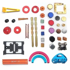
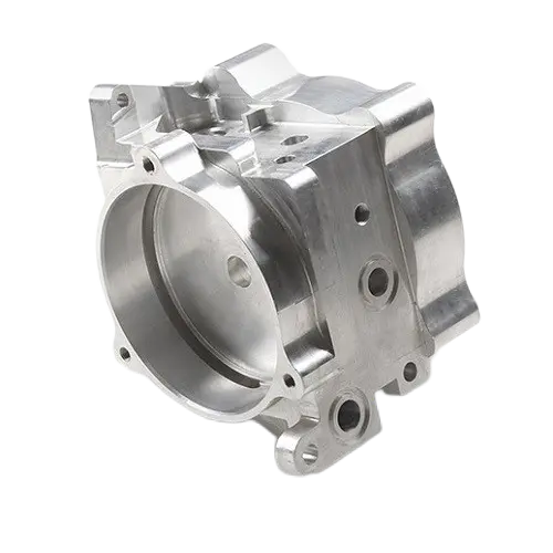
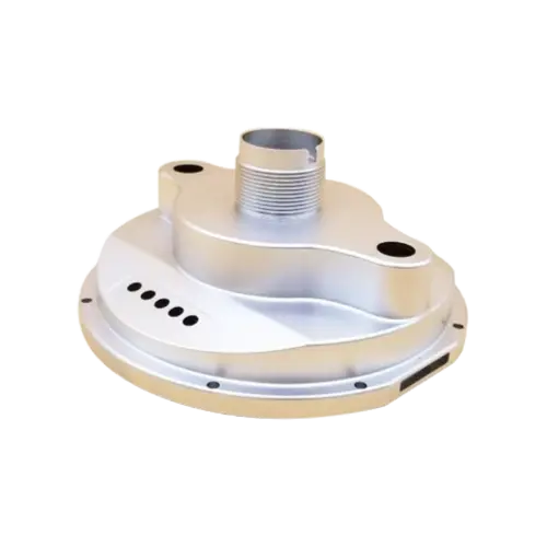
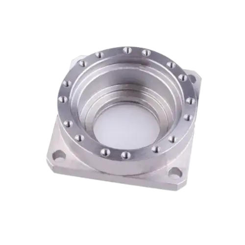
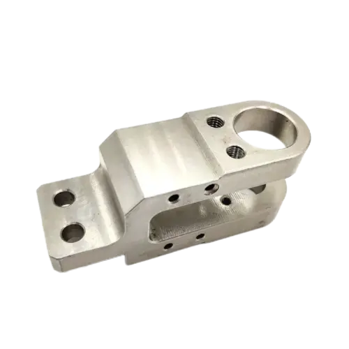
Related products of CNC Machining Bronze
-
Sale!Rated 0 out of 5Sale!Sale! Add to cart
$39.99Original price was: $39.99.$19.99Current price is: $19.99. -
Sale!Rated 0 out of 5Sale!Sale! Add to cart
$39.99Original price was: $39.99.$19.99Current price is: $19.99. -
Sale!Rated 0 out of 5Sale!Sale! Add to cart
$39.99Original price was: $39.99.$19.99Current price is: $19.99. -
Sale!Sale!Rated 5.00 out of 5 based on 1 customer ratingSale! Add to cart
$39.99Original price was: $39.99.$19.99Current price is: $19.99.


")


Reviews
There are no reviews yet.