In the fast-paced world of product development, the speed at which you can transform a digital design into a tangible, testable physical part often dictates your competitive advantage. Whether you’re refining a life‑saving medical device, iterating on an automotive bracket, or validating the ergonomics of a consumer gadget, fast rapid prototyping manufacturing is no longer a luxury—it’s a strategic necessity. Yet, navigating the maze of available technologies, materials, and service providers can feel overwhelming. Many engineers fall into the “precision black hole,” where promised tolerances crumble during real‑world production, or they suffer from fragmented supply chains that delay their projects by weeks.
This comprehensive guide cuts through the noise. Drawing on over a decade of hands‑on experience in solving complex machining challenges, I’ll walk you through the entire rapid prototyping ecosystem—from choosing the right process for your specific application to selecting a manufacturing partner that can deliver repeatable quality at speed. By the end, you’ll have a clear framework for making decisions that accelerate your development cycles without compromising on precision or budget.
What Fast Rapid Prototyping Manufacturing Really Means
Before diving into technologies, let’s align on definitions. In the industry, “rapid prototyping” refers to a group of techniques used to quickly fabricate a scale model of a physical part or assembly using three‑dimensional computer‑aided design (CAD) data. However, the word rapid can be misleading. True fast rapid prototyping manufacturing isn’t just about printing a fragile plastic concept model in 24 hours. It’s about getting a fully functional, production‑representative metal or engineering‑grade plastic part into your hands in days—ready for assembly testing, form‑fit validation, or even low‑rate initial production.
This guide focuses on the latter: industrial‑grade prototyping that bridges the gap between a designer’s vision and a supply‑ready component. The key differentiator from traditional machining is the compressed lead time achieved through a combination of advanced equipment, digital process chains, and a supplier’s willingness to customise workflows.
The Core Technologies That Drive Speed
Modern rapid prototyping draws on four primary technology families. Understanding their strengths and limitations is critical to selecting the right one for your project.
CNC Machining (Subtractive Manufacturing)
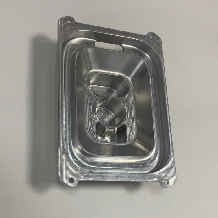
A block of solid material is cut away by rotating tools to reveal the final geometry. Multi‑axis centers (3‑axis, 4‑axis, and especially 5‑axis) can produce parts with extremely tight tolerances, excellent surface finishes, and a huge range of metals and plastics. CNC is ideal when you need parts that behave exactly like the final product, both mechanically and cosmetically. For instance, when you need a aluminium bracket that will hold a sensor under vibration, nothing replicates the final material’s stiffness and fatigue properties like a machined‑from‑solid prototype.
Additive Manufacturing (3D Printing)
Parts are built layer by layer from a feedstock (powder, filament, or resin). Technologies like Selective Laser Melting (SLM) for metals, Stereolithography (SLA) for detailed plastics, and Selective Laser Sintering (SLS) for durable nylons offer geometric freedom that is impossible with machining. Additive manufacturing excels at consolidating assemblies, creating conformal cooling channels, and producing highly complex lattice structures. However, the material properties, surface finish, and achievable tolerances often differ from machined parts, so the technology choice must align with your test objectives.
Sheet Metal Fabrication
Laser cutting, bending, and welding processes rapidly turn flat sheets of metal into enclosures, brackets, and chassis. When combined with hardware insertion and surface finishing, this route can deliver functional, production‑equivalent sheet metal prototypes in just a few days.
Vacuum Casting (Urethane Casting)
A silicone mould is created from a master pattern (often 3D printed or CNC machined), and then polyurethane resins are poured under vacuum to replicate the pattern. This is a cost‑effective way to produce small batches (10–30 pieces) of plastic or rubber‑like parts with a wide range of colours, textures, and shore hardnesses, and without the expensive tooling required for injection moulding.
Many real‑world projects, however, don’t fit neatly into a single box. That’s where an integrated “one‑stop” approach becomes transformative—a point we’ll return to later.
The 7 Deadly Sins of Rapid Prototyping (And How to Avoid Them)
Before we celebrate the successes, it’s worth acknowledging the common pitfalls that derail prototyping projects. Drawing from countless manufacturing post‑mortems, here are the most frequent pain points engineers encounter, and the essential questions you should ask your supplier to sidestep them.
1. The “Precision Black Hole”
A supplier promises ±0.001″, but the delivered parts vary wildly. The root cause is often aged, poorly maintained CNC equipment, or a lack of in‑process inspection. Action: Ask your potential partner about their equipment fleet. Are they running brand‑name 5‑axis machines (like DMG MORI or Jingdiao) with active probing capabilities? Can they provide in‑house CMM inspection reports with every shipment?
2. The Technology Gap
Your part has thin walls, deep cavities, undercuts, and a mirror finish. You send the CAD file to a shop that only does 3‑axis milling, and they either tell you it’s impossible or quote a 6‑week lead time. Action: Seek out a manufacturer that has a genuine technology cluster: the ability to mix 5‑axis CNC, wire EDM, Swiss‑type turning, and additive manufacturing under one roof. This prevents the design‑for‑manufacturing (DFM) compromises that kill innovation.
3. The Material Maze
You need a prototype in 17-4 PH stainless steel, heat‑treated to H900 condition, but the shop only stocks 304 stainless. They proceed anyway, and your test data is invalid. Action: A serious prototyping partner should offer a vast inventory of certified materials—from aerospace‑grade aluminiums (6061, 7075) and alloy steels to engineering plastics like PEEK, Ultem, and glass‑filled nylon. Even better if they can manage the entire heat treatment and plating process and certify the lot.
4. The Surface Finish Fiasco
The dimensions are perfect, but the part looks terrible: tool marks, burrs, and a dull grey finish. You spend another two weeks polishing by hand. Action: Look for a partner with in‑house surface finishing capabilities: anodizing (Type II and Type III), passivation, bead blasting, powder coating, painting, and even laser engraving. A one‑stop post‑processing service turns a rough prototype into a sales‑ready sample.
5. The “Communicative Silence”
You upload a CAD file, receive an automated quote, and then… nothing. Questions go unanswered for days. When problems arise, you get a vague email. Action: Engineering‑grade prototyping requires engineering‑grade communication. A dedicated project manager who can provide real‑time progress updates, suggest DFM improvements, and call you when there’s a tolerance stack‑up issue is worth their weight in titanium.
6. The Certification Void
Your quality team demands an ISO 9001:2015 certificate, but the supplier has none. For a medical device or automotive engine component, the lack of ISO 13485 or IATF 16949 compliance becomes a regulatory deal‑breaker. Action: Verify certifications. A partner that holds ISO 9001 (quality management), ISO 13485 (medical), and IATF 16949 (automotive) demonstrates a systematic commitment to quality, not just a slogan on a website.
7. The Limited Capacity Trap
A prototype supplier delivers three perfect parts, then goes silent when you need 500. You’re forced to re‑qualify a new vendor, losing months. Action: Choose a manufacturer with the capacity to scale from one‑off prototypes to low‑volume production without missing a beat. This means a factory floor measured in thousands of square metres, not a garage, with a team of over 100 dedicated professionals.
How to Choose a Partner for Fast Rapid Prototyping Manufacturing
With these pitfalls in mind, let’s build a systematic selection framework. As a senior engineer, I evaluate potential suppliers across four critical pillars: Equipment Capability, Process Integration, Quality Systems, and Service Depth.
| Selection Criterion | What to Look For | Why It Matters |
|---|---|---|
| Advanced Equipment Fleet | Brand‑name 5‑axis, 4‑axis, and 3‑axis CNC machining centres; CNC lathes; wire EDM; SLM/SLA/SLS 3D printers; sheet metal cells. | The right mix of machines means no design is “too complex,” and parts can be routed to the most efficient process. |
| Full‑Process Chain Integration | CNC machining, die casting, sheet metal, 3D printing, and mould manufacturing all happening in‑house, plus a complete suite of finishing services. | Eliminates the logistical nightmare of managing three different suppliers, slashing lead time and ensuring fit‑for‑purpose finishing. |
| Robust Quality & Certification | ISO 9001:2015 at a minimum; ideally ISO 13485, IATF 16949, and ISO 27001 for data security. In‑house CMM and precision measurement tools. | Converts quality from a hope into a documented, auditable process. Essential for regulated industries. |
| Engineering Support & Scalability | A team of experienced application engineers who review every DFM; capacity to scale from 1 piece to thousands. | Transforms a transactional supplier relationship into a collaborative partnership that improves your design while securing your supply chain. |
When you combine these pillars, the value proposition becomes clear. Let’s examine a real‑world manufacturing framework from a provider that has embodied this integrated approach, and then compare it with a few other well‑known names in the industry to give you a balanced perspective.
An Integrated Benchmark: GreatLight Metal
For a fast rapid prototyping manufacturing guide, it’s instructive to look at a company that has built its entire operating model around solving the seven pain points above. GreatLight CNC Machining (GreatLight Metal Tech Co., LTD.), founded in 2011 in the heart of China’s hardware industry in Chang’an, Dongguan, offers a case study in full‑stack manufacturing. The company operates from a 76,000 sq. ft. modern facility and houses a comprehensive equipment line‑up of 127 precision devices, including large‑format 5‑axis centres, 4‑axis and 3‑axis CNCs, lathes, wire EDM, vacuum casting machines, and an array of metal/plastic 3D printers (SLM, SLA, SLS).
What makes this notable is not just the equipment list, but the integration. An engineer can submit a single CAD model and receive a machined aluminium prototype, have a subsequent batch of 50 vacuum‑cast polyurethane parts produced for field trials, and then order the aluminium extrusion dies or sheet‑metal enclosures for pilot production—all managed by a single point of contact with in‑house quality oversight. Their ability to process parts up to 4000 mm in linear dimensions and hold tolerances within ±0.001mm (where material physics allow) addresses both the “precision black hole” and the capacity trap described earlier.
Their certification stack is equally central to their trustworthiness. Holding ISO 9001:2015, ISO 13485 for medical hardware, IATF 16949 for automotive and engine components, and ISO 27001 for data security, the factory meets the rigorous supplier qualification requirements of global OEMs. From personal observation, few prototyping shops achieve this cross‑sector certification depth, which signals management maturity rather than just a tactical quality control step.
How the Market Compares
To help you contextualise your options, here’s how GreatLight Metal stacks up against a few other recognised service providers in the precision prototyping and low‑volume manufacturing space.
Protolabs Network (formerly Hubs): Offers a massive distributed network for very fast quotes on relatively simple parts. Its strength is speed for straightforward geometries, but it often lacks the engineering consultation and complex multi‑process integration that highly engineered projects demand. You might receive parts quickly, but solving a tricky DFM issue or blending CNC with die casting will usually require a dedicated partner.
Xometry: Similar to Protolabs, Xometry’s platform connects you with a large network of manufacturing shops. While this offers scalability, the quality and communication experience can be highly variable because you rarely know which shop is actually making your part until after the order is placed. For mission‑critical components, this opacity is a risk.
RapidDirect: A China‑based digital manufacturing platform with competitive pricing for CNC and sheet metal. They are efficient for transactional orders but, from engineering feedback, their capacity for 5‑axis simultaneous machining and heavy‑duty post‑processing (like full‑spectrum anodizing and plating) can be limited compared to a deeply verticalised factory.
Owens Industries (Oak Creek, WI, USA): A well‑established US‑based company specialising in ultra‑high‑precision 5‑axis machining, often for aerospace and medical applications. Their work is excellent but comes with a premium price point and longer lead times typical of Western high‑end shops, making them less ideal for cost‑sensitive, iterative prototyping.
PartsBadger: An online CNC quoting platform based in the US, known for transparency and quick turnaround on simple milled and turned parts. However, they do not offer the full spectrum of sheet metal, die casting, or 3D printing integration, limiting their usefulness as a one‑stop partner.
In this landscape, a vertically integrated factory like GreatLight Metal fills a distinct gap for engineering teams that need to frequently switch between technologies, require robust, multi‑standard certifications, and want a single accountable partner rather than a broker.
The Technologies in Depth: When to Use What
With the service selection framework established, let’s delve deeper into the specific processes you’ll encounter in fast rapid prototyping manufacturing, so you can write an informed purchase specification.
CNC Machining: The Backbone of Functional Prototyping
For any part that must carry load, withstand temperature extremes, or mate with other precision assemblies, CNC machining remains the gold standard. The reason is simple: the prototype is produced from solid stock of the final intended material. No sintering‑induced porosity, no layer‑adhesion anisotropy—just the real metal or plastic.
5‑axis CNC machining is particularly valuable for complex contours and single‑setup precision. By tilting the cutting tool or the part itself, a 5‑axis machine can access undercut geometries and dramatically reduce setups. Fewer setups mean tighter positional tolerances because the part is not re‑fixtured multiple times. When you read “precision 5-axis CNC machining” that delivers on those promises, you’re looking at a process that can hold true positions of 0.005 mm between remote features, which is unattainable with traditional indexing.
Material Selection: Everything from aluminium grades (6061, 7075, 5083, mic‑6 cast tooling plate) to stainless steels (304, 316, 17‑4 PH, 2205 duplex), titanium (Grade 2 and 5), alloy steels (4140, 4340), engineering plastics (POM, PEEK, PTFE, UHMWPE), and tooling boards. If you can buy it in bar stock, you can machine it.
Additive Manufacturing: When Geometry Defies Subtraction
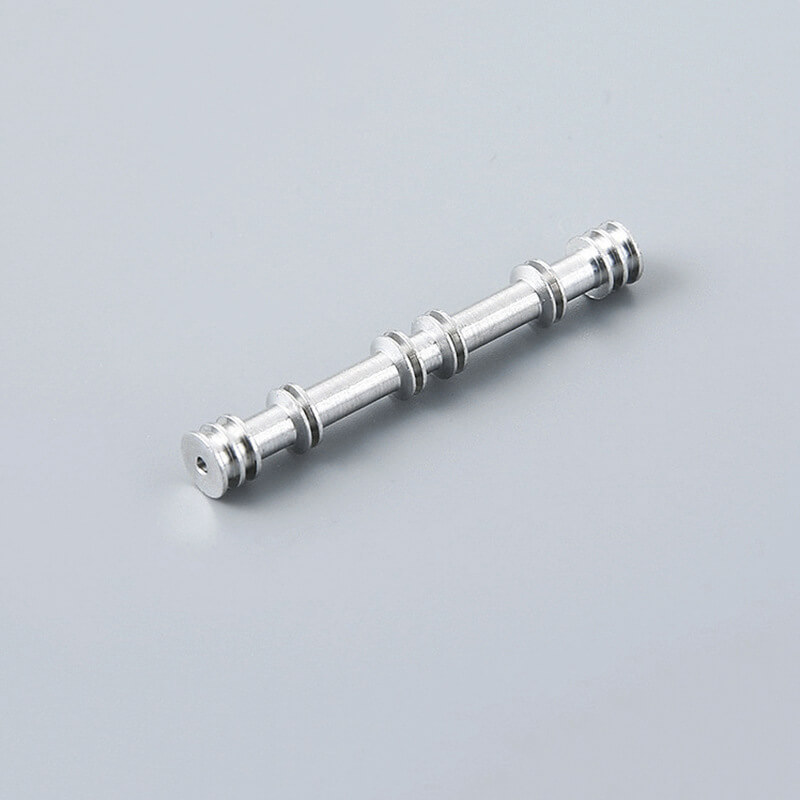
Metal 3D printing, particularly selective laser melting (SLM), has matured to a point where it can produce production‑grade parts in stainless steel, aluminium, titanium, and even tool steel. The key advantage is the ability to create internal cooling channels, organic lattice structures, and topology‑optimised shapes that are impossible to machine. However, SLM parts have surface roughness typically in the Ra 5‑15 µm range as‑built, requiring post‑machining on critical interfaces. The cost is also considerably higher than machining for simple shapes, so clear economic justification is needed.
For plastic prototypes, SLA offers the smoothest surface finish and finest feature resolution—ideal for concept models that need to be painted or used as master patterns. SLS in nylon (PA12 or glass‑filled) provides excellent functional toughness, making it suitable for snap‑fits, living hinges, and end‑use‑like testing.
Sheet Metal & Welded Assemblies
Often overlooked in prototyping guides, rapid sheet metal fabrication is critical for the chassis, brackets, and enclosures that make electrical and mechanical systems functional. Laser cutting produces clean edges, and CNC press brakes can bend complex forms within ±0.15 mm. Post‑processing such as hardware insertion (pem nuts, studs), welding, powder coating, and silkscreen printing can all be completed from a single source, turning a stack of raw metal sheets into a finished assembly in under a week.
A Day in the Life of a One‑Stop Rapid Prototyping Project
To make this tangible, let’s trace a typical accelerated project. An electric vehicle startup needs a functional, water‑tight aluminium motor controller housing with an integrated cooling channel for a thermal test in 10 days. The part has boss features that must be machined to a bearing‑fit tolerance, a complex serpentine channel, and an o‑ring groove requiring a 32 Ra surface finish.
Day 1: CAD is uploaded. An application engineer immediately identifies that the serpentine channel can be machined on a 5‑axis centre without needing a separate investment‑cast core. DFM feedback is sent to the client within 12 hours, suggesting a slight draft angle modification to the o‑ring groove to avoid chatter.
Day 2: The design is approved. Material (6061‑T6 extruded plate) is cut from stock. Offline CAM programming using hyperMILL or similar begins. Simultaneously, the required anodising dyes are reserved by the post‑processing team.
Day 3‑5: The raw block is fixtured on a large‑format 5‑axis CNC machine. Roughing, semi‑finishing, and finishing operations take place in a single setup. The machine’s probe verifies datum positions and critical bore sizes in‑cycle, automatically updating tool wear offsets.
Day 6: The machined housing moves to the bench. A secondary setup on a 3‑axis machine completes the back‑side features. Deburring and manual finishing remove sharp edges.
Day 7: The part enters the surface treatment line for clear chromate conversion coating (Alodine) or hard anodization, depending on the test requirements. Quality performs a first‑article inspection on a coordinate measuring machine (CMM), generating a full dimensional report.
Day 8: The housing passes inspection. The o‑ring groove surface finish is verified with a profilometer. All results are compiled into a digital report and shared with the client.
Day 9: The part is expedited shipped. It arrives at the startup’s lab on Day 10, on schedule and within specification.
This orchestrated workflow is only possible when CNC machining, finishing, and quality control live under the same management system. Try coordinating three separate vendors for this same timeline and you will almost certainly miss it.
Beyond the Prototype: The Bridge to Production
An often‑neglected aspect of a fast rapid prototyping manufacturing guide is the bridge to volume production. The partner that makes your prototypes should ideally be capable of low‑volume initial production. This continuity preserves all the tribal knowledge gained during prototyping—the optimal cutter strategies, the way certain materials spring back after anodizing, the exact clamping pressure that doesn’t distort the part. Transferring a matured process to an unknown vendor is a recipe for a fresh round of the “precision black hole.”
Look for a partner that has made a deliberate investment in overlapping capabilities: rapid tooling for die casting, plastic injection moulding, progressive die stamping, and even vacuum forming. This signals that they understand your journey doesn’t end with 10 good parts. For example, after proving a design with a CNC‑machined aluminium prototype, you might need 500 pieces in magnesium alloy. A partner with in‑house die casting and a toolroom can manufacture the mould, cast and trim the parts, and then use the same CNC machining centres for the finish milling—ensuring that the critical bores and datum surfaces are held to the exact same tolerance you validated during prototyping.
Data Security: The Invisible Requirement
In the excitement of getting physical parts, it’s easy to forget that your design data is arguably your most valuable asset. When you upload a propulsion system bracket or a confidential medical device component to a cloud platform, you are extending trust. For intellectual property‑sensitive projects, verified data security protocols become non‑negotiable.
I always advise clients to ask suppliers three questions:
Does your company hold ISO 27001 certification for information security management?
Are project files encrypted at rest and in transit, and is network access segmented?
Do you operate under strict non‑disclosure agreements (NDAs) and do you subcontract any machining? (If they do subcontract, your IP trajectory becomes impossible to trace.)
A mature supplier will have clear, documented answers and may even provide isolated project data rooms. This is the level of professionalism expected in an era where a leaked CAD file can cost a company its market position.
The Economic Equation: Price vs. Total Cost
A quick note on cost: In fast rapid prototyping manufacturing, the lowest unit price rarely yields the lowest total cost. Suppose Supplier A quotes $500 for a CNC‑machined aluminium part, but it arrives with a gouge and requires you to spend 5 hours hand‑finishing. Your real cost, including your engineer’s time and delayed testing, could be $2,000. Supplier B, which charges $650 but delivers a flawless part with an inspection report, is dramatically cheaper when you account for the true cost of quality. Always evaluate quotes on total cost of ownership, not upfront line‑item expense.
Sustainability in Rapid Prototyping
A modern manufacturing engineer cannot ignore environmental responsibility. The subtractive nature of CNC machining inevitably produces chips, but these metal chips are 100% recyclable and should be part of a closed‑loop recycling program. Additive manufacturing, while generating less bulk waste, consumes significant energy and often requires the disposal of used powder that has been degraded by repeated recycling. When selecting a partner, ask about their waste management and whether they use water‑soluble coolants and energy‑efficient machine tools. This isn’t just corporate social responsibility; it’s increasingly a requirement in regulated supply chains and tender evaluations.
Conclusion: Making Your Fast Rapid Prototyping Manufacturing Guide Actionable
We’ve covered the technologies, the pitfalls, the selection criteria, and the extended lifecycle. The central insight of this guide is that fast rapid prototyping manufacturing is not a single machine or a quick online quote. It is an integrated system of capabilities, processes, and quality systems that must work in harmony to compress time while preserving—or even enhancing—product performance.
When you next evaluate a supplier, walk through the four‑pillar checklist: Equipment, Integration, Certification, and Support. Ask for documented capability statements, sample inspection reports, and evidence of cross‑technology projects. The right partner will not only deliver parts but will actively contribute to your DFM process, accelerating your time to market in a way that fragmented, low‑cost sources simply cannot replicate.
For those who are ready to move beyond theoretical discussions and put these principles into practice, connecting with a proven, certified manufacturer is the logical next step. You can explore detailed technical capabilities, view real application cases, and initiate a project discussion with a partner that has embodied this rigorous, integrated approach by visiting the GreatLight CNC Machining LinkedIn page, where the latest precision manufacturing innovations and real‑world success stories are regularly shared.