Absolutely, yes. OpenSCAD files can be effectively used as the starting point for creating parts with CNC machines. While OpenSCAD itself does not output a direct CNC machine code (like G-code), it serves as a powerful and precise parametric 3D modeling engine. The 3D models you design in OpenSCAD can be exported into universally recognized formats that any professional CNC machining service, like GreatLight CNC Machining Factory, can then utilize to program and manufacture your part.
This synergy between parametric design and precision manufacturing opens up a world of possibilities for engineers, designers, and hobbyists. Let’s delve into how this workflow functions, its advantages, and the critical considerations for a successful outcome.
The Core Workflow: From OpenSCAD Script to Physical Part
The process of turning an OpenSCAD file into a CNC-machined component involves several key steps:
Design & Modeling in OpenSCAD: You create your 3D model using OpenSCAD’s scripting language. This is where you define all dimensions, geometric relationships, and tolerances with code. The parametric nature is key—changing a single variable (e.g., hole_diameter = 6.5) updates the entire model, ensuring perfect consistency.
Export to a Neutral 3D Format: Once your design is final, you render it in OpenSCAD and export it as a 3D mesh file. The most common and recommended format is STL (Stereolithography). Other viable formats include STEP or IGES, which are better for preserving precise geometric data (curves, surfaces) rather than tessellated facets, though generating these directly from OpenSCAD may require add-ons or conversion in another CAD package.

Import into CAM Software: The manufacturing partner (like GreatLight CNC Machining Factory) imports your STL or STEP file into their Computer-Aided Manufacturing (CAM) software. This is where the manufacturing magic happens. A skilled CNC programmer analyzes your model, selects the appropriate tools (end mills, drills), defines toolpaths, calculates cutting speeds and feeds, and sets up work-holding strategies.
G-code Generation & Simulation: The CAM software translates the toolpaths into G-code, the low-level language that instructs the CNC machine on every movement. Modern CAM systems run detailed simulations to detect potential errors like tool collisions or inefficient paths before any metal is cut.
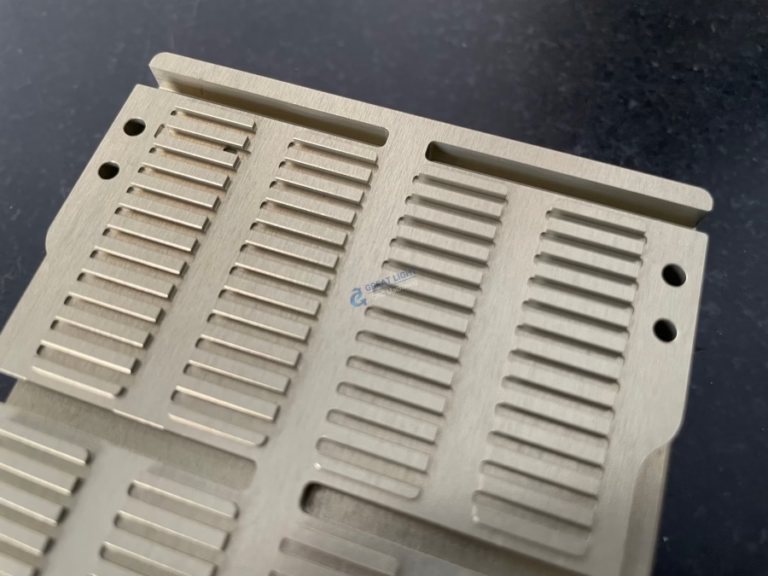
Precision Machining: The validated G-code is loaded onto the CNC machine—whether a 3-axis mill for simpler parts or a sophisticated five-axis CNC machining center for complex geometries. The machine then precisely cuts the part from a solid block of your chosen material (aluminum, stainless steel, plastic, etc.).
Post-Processing & Inspection: The part is deburred, finished (e.g., anodizing, polishing), and rigorously inspected using tools like Coordinate Measuring Machines (CMMs) to ensure it matches the dimensions specified in your original OpenSCAD design.
Key Advantages of Using OpenSCAD for CNC Machining
Unmatched Design Precision and Consistency: The script-based approach eliminates the “mouse-slipping” inaccuracies possible in graphical CAD. Every feature is mathematically defined, which is ideal for parts requiring exact fits, such as jigs, fixtures, or engine components.
Effortless Design Iteration and Version Control: Need to make a version with a 10mm hole instead of an 8mm hole? Change one variable, re-render, and export. This parametric control is a boon for prototyping. Furthermore, the .scad file is plain text, making it perfect for version control systems like Git, allowing you to track every change to your design.
Ideal for Algorithmic and Customizable Designs: OpenSCAD excels at creating parts based on formulas or user-defined parameters (e.g., custom gear profiles, fractal-like structures, or client-customizable brackets). This makes it powerful for creating families of parts or highly optimized, generative designs.
Open Source and Cost-Effective: For individuals and startups, OpenSCAD provides a professional-grade parametric modeling capability without the high cost of some commercial CAD licenses.
Critical Considerations and Best Practices
To ensure your OpenSCAD design is not just manufacturable but optimized for CNC machining services, follow these guidelines:
Understand Design for Manufacturing (DFM): A model that looks perfect on screen may be impossible or prohibitively expensive to machine. Consider factors like:
Internal Sharp Corners: A cutting tool is round, so it cannot create a perfectly sharp internal corner. Design with appropriate fillets (radii) that match standard end mill sizes.
Feature Accessibility: Can a tool physically reach the area that needs to be cut? For deep cavities or complex undercuts, multi-axis machining may be required.
Wall Thickness: Ensure walls are thick enough to withstand machining forces without vibrating or breaking.
Tolerances: Clearly define critical tolerances in your design notes. For instance, specify hole_for_press_fit_bearing: diameter 12mm (+0.000/-0.015mm).
Export High-Quality STL Files: When exporting from OpenSCAD, use a high $fn (facet number) variable for curved surfaces. A low-polygon STL will result in a faceted, imprecise physical part. The smoother the STL, the more accurate the final machined surface.

Provide Comprehensive Documentation: Along with your STL file, always provide:

A detailed 2D drawing (PDF) with critical dimensions, tolerances, surface finishes, and material specification. (While OpenSCAD can generate 2D DXF exports, these are typically for 2D profiles; detailed drawings are often made in dedicated software).
The OpenSCAD script file itself. This can be invaluable for the manufacturer to understand design intent if a minor adjustment for manufacturability is suggested.
Clear notes on the part’s function and any critical features.
Leverage Professional Expertise: This is where partnering with an experienced manufacturer like GreatLight CNC Machining Factory becomes crucial. Our engineers review every design for DFM. We can identify potential issues early—such as suggesting a slight draft angle for a deep pocket or recommending a more machinable alloy—saving you time and cost on prototyping.
OpenSCAD vs. Traditional CAD for CNC: A Situational Perspective
Choose OpenSCAD when: Your design is highly parametric, based on mathematical relationships, part of an open-source project, or requires flawless geometric consistency. It’s superb for functional prototypes, tooling, and custom hardware.
Consider Traditional (GUI-based) CAD when: The design involves complex organic shapes (like consumer product casings), extensive assembly modeling, or requires direct integration with advanced surface modeling tools. Software like SolidWorks or Fusion 360 also have integrated CAM modules, creating a more seamless design-to-CNC path within a single ecosystem.
Conclusion
Can Openscad Files Be Used For CNC Machines? Not only can they be used, but they represent a formidable and precise approach to creating designs destined for precision parts machining and customization. The marriage of OpenSCAD’s rigorous, code-driven modeling with the advanced capabilities of modern five-axis CNC machining centers enables the creation of highly accurate, repeatable, and complex components. By following DFM principles and collaborating with a certified, experienced manufacturer like GreatLight CNC Machining Factory—which possesses the technical expertise to interpret your design intent and the advanced equipment to execute it flawlessly—you transform a powerful digital script into a high-quality, functional physical reality.
Frequently Asked Questions (FAQ)
Q1: I have an OpenSCAD file. What exact file should I send to a CNC machining quote request?
A: You should provide two key files: 1) The exported high-resolution STL file (or preferably a STEP file if you can generate/convert one), and 2) The original .scad source file. Additionally, a PDF drawing with critical dimensions and notes is highly recommended.
Q2: Are there any specific features in OpenSCAD that are problematic for CNC machining?
A: Yes. Be cautious with:
Extremely thin “paper-like” walls or features that are thinner than the minimum tool diameter (often around 1mm or 0.04″ for fine detail).
Boolean operations on highly tessellated models can sometimes create non-manifold edges (defects in the mesh). Always use render() before exporting to ensure a clean, watertight mesh.
Designs that assume perfect zero-radius corners. Always incorporate tool radius into your design logic.
Q3: My OpenSCAD part is very complex with many overhangs. Can it still be CNC machined?
A: It depends. Some overhangs may require 5-axis CNC machining, where the cutting tool can approach the part from multiple angles, eliminating the need for multiple setups. Other severe undercuts might be more economical to create using a different process, such as metal 3D printing (SLM) or by designing the part as multiple components to be assembled. A manufacturing engineer can advise on the best approach.
Q4: Why should I choose a manufacturer like GreatLight CNC Machining Factory for my OpenSCAD-designed parts?
A: GreatLight combines the technical proficiency to work with parametric design data with a full suite of ISO 9001:2015 certified processes. Our expertise in multi-axis machining allows us to handle the geometric complexity that often comes from OpenSCAD designs. We offer a true one-stop post-processing and finishing service, guiding you from your script file to a finished, anodized, or polished part, all while ensuring the precision you coded for is achieved in metal or plastic.


