01 What is geometric tolerance?
“The geometric characteristics” refer to the shape, size and location of the object, and “tolerance” is “an eligible error”. The “geometric tolerance” defines not only the size, but also defines eligible errors in the form and the position.
(1) The difference between size and geometric tolerance
The design method of design drawings can be roughly divided into two categories: “size tolerance” and “geometric tolerance”.
The dimensions of tolerance control are the length of each part. Control of geometric tolerance is the shape, parallel, inclination, position, beat, etc.
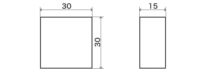
Dimension tolerance drawings

Image of geometric tolerance drawings
This means “the treatment of the” parallel “no more” 0.02 “of the show (A).
(2) The advantages of geometric tolerance
Why do you need to mark geometric tolerances? For example, when the designer ordered a plate -shaped part, the following signs were made by size tolerance.

However, depending on the drawings above, the producer can deliver the parts below.

These parts will become unsuitable or bad.
The reason is that parallelism is not marked on the drawings. The corresponding responsibility is not the processor processor, but the designer’s tolerance brand.
The drawing of the same part with geometric tolerance can be obtained as indicated below. Based on size information, the figure added geometric tolerance information such as “parallelism” and “flat degrees”. In this way, it can avoid the problems caused by the simple labeling of size tolerances.
The drawing of the same part of the difference can obtain the design drawings as indicated below. Based on size information, the figure added geometric tolerance information such as “parallelism” and “flat degrees”. In this way, it can avoid the problems caused by the simple labeling of size tolerances.

In summary, the advantages of geometric tolerances are the intentions of the designer that can be designed correctly and effectively to be reflected by tolerance to the size.
(3) Independent principle
Dimensive tolerances are different from the control of geometric tolerance. The size of the size and control of tolerance is length, and control of geometric tolerance is the relationship of shape and position.
Consequently, tolerance to size and geometric tolerance are not divided in advantages and disadvantages.
In addition, the size and geometric tolerances are measured in different measurement equipment and detection methods, respectively. For example, dimension tolerance will use a cashmere caliper, feet of a thousand meters, etc. To measure the distance between 2 points.


However, geometric tolerances will use the real circle measurement instrument and the three coordinated measurement instrument to detect the real circle and the position of the central axis. In other words, according to size tolerance, it will be considered qualified and geometric tolerance will not be qualified.
Therefore, we can think that the size of the control of tolerance and the control of geometric tolerance essentially have no correlation. This way of thinking is the “principle of independence”.
(4) Definition in ISO
The relationship between size and geometric characteristics is as follows.
ISO 8015-1985
With the exception of the situation which specifies the correlation, the requirements marked in the drawings, such as tolerance and geometric tolerance, have no correlation with all other sizes, tolerances or characteristics and play an independent role.
As mentioned above, the principle of independence is an international standard stipulated by ISO. However, in the United States and other countries, some companies can follow the ASME (American Mechanical Engineers Association) criteria that do not apply independence. Consequently, when making a business with overseas companies, it is recommended to negotiate and other channels in advance to clarify the specification requirements.
02 Drawings and symbols of geometric tolerance
Geometry tolerance is specified by symbols on the drawings. Currently, there are 16 symbols of geometric tolerances and classified according to the tolerance of control.
(1) Classification and symbol of geometric tolerance characteristics
The symbol of geometric tolerance is illustrated below. The “independent element” of the so-appeal element “element applicable” is the factors that do not associate the reference index (no reference). The “benchmark” is the theoretical ideal element to determine the attitude, the position and the beat. The “associated element” is the element associated with the reference, which is used to specify posture, location and jump tolerance.


List of geometric tolerance symbols (related specifications: ISO5459)
(2) Theory of actual location (size value surrounded by boxes)
The way of thinking of geometric tolerance (position, outline, inclination) with “Ted: Ted: Ted: Ted: Ted: Ted: Ted: Ted: Theretic exact dimension)”. TED will use a box (□) to surround the correct theoretical size and fill the tolerance of the tolerance linked to the position in the shape control box.
1) Specification of the location
When the position as indicated in the figure below is specified, the reference size and tolerance marked by the size tolerance will become the sum of the tolerance (accumulation tolerance) of the size tolerance, and the correct position does not Can’t be specified. When you use TED for labeling, as it does not attach tolerance, this will not cause cumulative tolerances.


2) Specify the tolerance area
During the specification of the tolerance area, the theory of the actual position will correctly indicate the position which must be controlled by TED.
At the time of the element, the tolerance zone is the circular (a) or spherical shape centered on this point; Public difference.

03 What is the reference (datum)
Comparative SO analysis (given) must be the basis, the line and the point that the reference index during the treatment and the measurement of the size.
(1) Definition in ISO
ISO 5459: 2011 Definition: Tolerance position zone (public tolerance) and / or posture (tolerance), or the ideal element of the real composition selected (more than 1) to define the ideal element of the state of the state of execution (more than 1) more than 1).
(2) Types of reference
The benchmarks are divided into “reference elements” and “simulation reference elements”. There are also more than 2 benchmarks, specifying the “reference system” of the specified elements.
Standard elements: real elements (surface, holes, etc.) to adjust the reference to adjust the reference.
Simulation reference element: Connect with the reference elements when defining the reference and the actual surface (tablet, bearing, heart shaft, etc.) with extremely precise forms.
Standard system: In order to define the reference index for tolerance elements, combine the combination of more than two reference groups with different landmarks.
The marked surface because the reference index has no perfect shape. Therefore, it is necessary to contact the tablet, the rule and heart trees with more precise surfaces as a practical reference for contact.

(3) Drawing of reference elements
The reference can be marked by the following symbols (reference symbols). The reference symbol is marked by a hollow or blackened triangle. The English letters representing the reference index must comply with the management of the drawings.

In addition, as an object zone, it will vary from the position of the reference symbol in the drawings. In order to rigorously transmit design intention, please pay attention to the position of the reference.
1) When marked axis or central plan
Merge the size line and the benchmark one place to mark the reference item. The center of the marked comparison factor will become the reference plan or the central reference plane.

2) When marking the house
The size line and the reference of the reference elements must be staggered when marked. The center of the marked comparison factor will become the reference plan or the central reference plane.

04 body control box
Geometric tolerance is marked by the “body control box”. The body control box must contain the following elements.

A: Geometric characteristic symbol
Mark the type of geometric tolerance.
B: diameter symbol (if necessary)
The geometric characteristics that must be marked are presented below.
The circular zone of the region in the two -dimensional plane: position, concentricity
The central zone of the cylinder in three -dimensional space: true rectitude, parallel, right angle, inclined, position, coaxiality
The central area of the sphere in three -dimensional space: position
C: geometric difference
The value of tolerance. The unit is “mm (mm)”.
D: physical tolerance, public tolerance area, etc.
It mainly includes “(maximum entity requirements)”, “(minimum entity requirements)”, “CZ (common area)”, etc. And others, etc.
E: priority benchmark
The designer must be defined as a reference as a reference. Mark a certain number of bases in time and mark it in the order from left to right, prior to low.
In normal circumstances, the designers will determine the benchmark letters in the order of priority, so the higher the higher letters, the higher the priority.
05 types of geometric tolerance
Currently, there are 14 symbols of the CCP of geometric tolerances. If you are classified in other ways, there are 15 symbols.
These symbols are divided into “form tolerances”, “posture tolerances”, “position tolerances” and “jump tolerances”.
“Maximum entity requirements” are essential in design such as the infusion of the tree.
(1) Skills tolerance (form deviation)
So-appeal tolerance is the basic geometric tolerance of the target shape (component). There are no benchmarks that can independently determine geometric tolerance.
1) Relax
Specify the parameter of “rectitude” and on how the lines must be presented. It is suitable for the straight line rather than flat objects, indicating the curved situation of the central line and the bus. Therefore, it can be used to configure long -size objects.
Label

Drawing
When the size of the cylindrical diameter is connected to the body control box, the cylinder axis must be located in a cylindrical 0.1 mm in diameter.
2) degree in plan
Specify the “convex surface and concavity”, and the marked flat surface must be presented. The highest part and the most depressed part must be separated between the two separate planes of the upper and lower plans.
Label

Drawing
The surface must be between two parallel planes with only 0.3 mm distance.
3) Real roundness
Specify the parameter of the “roundness”. It indicates the circular degree of a tree, a hole, a cone and other circles, and the sign must be indicated.
Label

Drawing
The external device of any section with a right album axis must be between two concentric circles between 0.1 mm separately on the same plane.
4) Circularity
Specify the parameters of “roundness” and “lidité”. To indicate the distortion of the cylindrical column, this indicates how the cylindrical shape must be present.
Label

Drawing
As an object of the object, it must be between two coaxial cylindrical surfaces with only 0.1 mm.
(2) Intelligent tolerance, position tolerance (line contour, surface outline)
The outline of the line is also used in tolerance and the face. The formation of the form control box in shape tolerance and position tolerance is the same.
1) Line contour
This is a parameter that labeling the design parts “if the real curved surface is consistent with the ideal value of the design”, which means the distortion of the outline line (the line element presented by the surface cutting surface). The section of the curved surface specified must be located in the tolerance area.
Label

Drawing
The outline of any cross section of the projection surface as an object must be placed on the correct theoretical outline, and between the two collar lines generated by a circle with a diameter of 0.03 mm.
2) Facial outline
Mark the parameters of the design parts “actual curve (surface), etc. with the ideal value of the design”. The surface area is different from the line outline degree, and the curved surface specified is subjected.
Label

Drawing
The object must be placed on the correct theoretical outline and between the two curves generated by a ball of a diameter of 0.1 mm.
(3) Gesture tolerance
Tolerance to the SO-SOVELED posture is tolerance which determines that the corresponding element should have a posture in relation to a certain reference. Before specifying tolerance to gestures, the reference must be determined, so attitude tolerance is the element associated with the reference, that is to say the geometric tolerance of the associated element.
1) parallel
Similar to the flat degree, there is a reference in parallel (as a reference plan, straight line). The degree in parallel specifies the “2 right plans or 2 parallels to each other”.
Label

Drawing
The noodles mentioned in the labeling line must be between parallel to the reference plane A, and the steering of the arrow of the labeling line is only between 2 plans with an interval of 0.05 mm.
2) Angle of rect
Specify the “good degree of accuracy” of the reference (as a reference plan, straight line). The digital unit specified from a right angle is not an angle, but MM.
Label

Drawing
The plane mentioned by the arrow of the line must be located in a cylinder with a diameter of 0.03 mm perpendicular to the reference plane A.
3) Sites
When the straight line and the specified plan are not at 90 °, the specified “if the reference (as a reference plan and the straight line) presents the correct tilt state”. The digital unit specified by the inclination is not an angle, but MM.
Label

Drawing
The noodles mentioned in the labeling line must be exactly the theoretical inclination of 45 ° with precision with the reference plan A, and it is located between two parallel planes with only a 0.3 mm interval with the direction of the Arrow of the label line.
(4) tolerance to the location
The SO-appeal position tolerance consists in determining the tolerance of the elements corresponding to the location (real location) of the corresponding element. Before specifying position tolerance, the reference must be determined.
1) Location
Specify the accuracy of the “position correction in relation to the reference (as a base, straight line)”.
Label

Drawing
The central point of the circle mentioned by the arrow of the labeling line must be located in a circle with a diameter of 0.1 mm.
2) Coaxiality
Specify the “degree of the axis of 2 cylinders (no deviation from the central axis)”.
Label

Drawing
The cylindrical axis mentioned at the arrow of the marking line must be located in a cylinder with a diameter of 0.03 mm with a diameter of 0.03 mm in the line of reference axis A.
3) Discussion
Specify the accuracy of “the degree of the coaxial axis (no deviation) of the two cylinders”. The difference with coaxiality is that the reference element is the central point (plan).
Label

Drawing
The cylindrical axis referred to the arrow of the marking line must be located in a cylinder with a diameter of 0.05 mm in diameter of 0.05 mm in the line of reference axis A.
4) Symmetry
Specify the accuracy of “symmetry in relation to the reference (such as the reference)”.
Label

Drawing
The central surface called arrow of the marking line must be between two parallel planes with a symmetrical interval with the central reference A plan of 0.05 mm.
(5) Specter tolerance (deviation of the bump)
“Beat tolerance” consists in defining a straight line on a rotary axis, turning the target (component) and geometric tolerance of the jump value of the target element. Before specifying the jump tolerance, the reference must be determined.
1) Round beat
The specified part is “jumping into the weekly part” during rotation. Beat round -Ci is, the beat of the measurement value when the rotating parts must be in the prescribed beach.
Label

Drawing
When a rotation of the straight line of the basal axis for 1 week, on any vertically measurement plane on the straight line of the reference axis, the radius of the cylindrical surface mentioned by the arrow of the line arrow does not must not exceed 0.03 mm.
2) Complete Jump
The specified part “beating the entire surface during the rotation”. The full jump-that is to say that the jump of the overall measurement value of the cylindrical surface must be in the specified beach.
Label

Drawing
When the cylindrical part is turned around the straight line of the basal axis, any point on the surface of the cylindrical cylinder, the direction of the radius of the cylindrical surface mentioned by the arrow of the arrow of the line must not exceed 0, 03 mm.
(6) Maximum entity requirements (MMR) and minimum entity requirements (LMR)
Maximum entity requirements (MMR: maximum material requirement) are used to mark the tolerance of chimerical components such as tree holes. The minimum entity requirements (LMR: The least materials) are used to specify the resistance and the thickness of the pipeline of the holes around the end of the final surface.
1) Method
When the maximum entity requirements are applicable to a certain size, it is necessary to mark after the geometric tolerance value, or after the reference symbol in the body control box. When applying minimum entities, it must be marked.
Label

2) The advantages of the maximum entity requirements and minimum entity requirements
It can correctly implement the management and control linked to the volume depending on the difference in the difference of size and geometric tolerance, which can reach reasonable tolerance parameters. When used for tolerances such as trees and holes, it can correctly express the volume of parts and has the advantages of reducing treatment costs and improving quality.
Daguang focuses on providing solutions such as precision CNC machining services (3-axis, 4-axis, 5-axis machining), CNC milling, 3D printing and rapid prototyping services.


