The car molding composite is a technique for using the car milling synthesis. Start of Tracyl and the corresponding program loop corresponding to the Tracyl function, and the conversion programming of the tracyl column of the sculpture cycle.
1 preface
Car composite and milling machines complete a variety of processing processes via a part of a part clip. The composite of the car and the milling is an advanced cutting method which uses the synthesis of the rotation of the strawberries and the rotation of the parts to obtain the process of cutting parts in geometric precision and the treatment of the integrity of the surface surface . The composite treatment of the car and the grinding are not simply merged the two methods of car treatment and the molding to a machine. and technology[1-3]Essence This article takes the Siemens 828D system as an example to introduce the car programming method and the composite of the Siemens car.
2 The advantage of the Siemens CNC system
Siemens 828D provides a very practical human dialogue programming. There is no real y axis in most tower structures. However, it is difficult to calculate the position of the main spindle angle with the X and Z axis, and the Siemens CNC system is suitable for this request.
During the periability of the treatment of circular grinding, the “tracyl (d)” is used for the surface conversion of the column. Final facial conversion, the system will automatically generate a virtual y axis. Here are common instructions for the surface of the column and the grinding of the End facial car.
Setms (N);
Setms; Resetting the main axis
Diamond; diameter programming
To transmit;
Tracyl (D); The surface conversion of the column begins, where the value of the parameter D is the diameter of the cylindrical part
Trafoof;
3 cars
3.1 Use the crushing parts of the surface column of the Tracyl column to sell parts
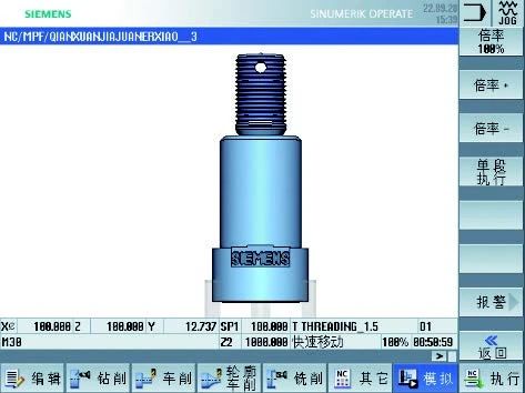
The surface treatment axis of the surface of the tramon composite tracyl tramonl column, first use the Siemens Man -Machine dialog module to treat the parts around and thread the parts, then treat the perforation on the thread side, then By crushing the part of the room, and finally carved the letters on the flat square. The axis of the finished product is illustrated in Figure 1.
Figure 1 Sale of finished products
The interface of the tree and the script screw is illustrated in Figure 2, and the programming of the Simon subsystem module is used.

fig
After the treatment of the outside circle and the wire, the first step should pierce two perforations in the part of the axis wire. First, choose the required tool. The drilling of the cylinder with a diameter of 24 mm and Z in the direction of the outer circle begins to pierce on the cylinder with a direction of -6 mm. -28 here. After piercing the hole, the conversion is finished, using Trafoof to cancel the conversion and reset of the main axis. The specific program is as follows.
T4D1
Espos = 0
Setms (2)
M3S1000F80
Tracyl (24)
G01Z 6
X-28
X25
Trans
Sets
Another machining program for perforation is fundamentally the same, only “ESPS = 90” is required. The parts after the end of the exercise are presented in Figure 3.

3 -piece figure once the exercise is finished
The second step requires a symmetrical flat square with axis sales. First, select the tool. In the Zirling pillar with a 40 mm cylindrical in the direction Z of the Z direction, the milling tree of the second axis is reset once the grinding is finished once the grinding is finished. The specific program is as follows.
T6D1
Espos = 0
Setms (2)
M3S1000F80
G01Z95
X40
Y30
Y-30
X36
Y30
Y-30
Sets
The other side should only change “Espos = 180”. The milling part is illustrated in Figure 4.

Figure 4 The parts terminated by milling
The third step should be engraved with a cylindrical surface outside the axis, and the main axis of the Tour is necessary to follow the grinding axis of the second axis and start the surface conversion control of the column of Tracyl. First, choose a tool. Use the Siemens sculpture module on the zimme cylinder of the zimon -70 mm zimes and the x direction of 38 mm for the treatment. The part of the sculpture is illustrated in Figure 5. The specific program is as follows.
T8D1
Espos = 0
Setms (2)
M3S1000F80
Tracyl (38)
Cycle60 (“Siemens”, 100.19.5 ,, 0.75,0,70,0,0,8,1,8,0.1,1001,000,1252,0,100,13,13)
Trans
Sets

Figure 5 The parts ended by sculpture
If you need to sculpt on the plane, delete the “Tracyl (38)” program and position the spindle to the angle required to sculpt.
T8D1
Espos = 0
Setms (2)
M3S1000F80
Cycle60 (“Siemens”, 100.17.5.5 ,, 0.75,0.95,0,0,0,7,2.0.1,1000,2001,000,1252,0,100,13,13)
Trans
Sets
The parts ended by plane sculpture are illustrated in Figure 6.

Figure 6 pieces terminated by flat sculpture
The engraving function can also be carved on the part and the product flow number.
3.2 Use the transmission of the TERMINAL SUPERMINAT
Translate the treatment sleeve through the car and molding of the composite machine, then use the Siemens module first in dialogue to complete the parts of the parts, then convert the drilling hole through the transmission end surface, And finally the face grinding cavity.
The round car of the sleeve is illustrated in Figure 7, using the programming of the Simon subsystem module.

Figure 7 Circular cylindrical circular cars set
Once the race is finished, the first step should be drilled at the end of the English Channel. First, choose the need for a tool. Taking the center of the part of the parts as the center of the round and the 15 mm radius as a radius, the circular drill hole is made. The specific program is as follows.
T5D1
Espos = 0
Setms (2)
TO TRANSMIT
M3S1000F80
Mall cycle83 (100,0,1,31 ,,, 5,90.0.6.0.6.90,0,0,2,1.4,0.6,6,0,0,1,121112)
Kong3: Holes2 (0.0,14.5,30,30,101010,0 ,,, 1)
Malice
Trans
Sets
G0Z100.0
Once the exercise is finished, the piece is illustrated in Figure 8.

Figure 8 parts terminated by drilling
The second step requires a square groove in the final surface of the Channel. First, choose the required tool. In the center of the part of the part of the part, the side of the milling slot is 15 mm square. The specific program is as follows.
T7D1
Setms (2)
TO TRANSMIT
M3S1000F80
Pocket3 (60.0.5,4.15,15,5,0,0,30,2,0,1000,1,1,0,21,80,3,15,2 ,2, 0, 1,2,1100,11,11)
Trans
Sets
G0Z100.0
The part of the milling location is illustrated in Figure 9.

Figure 9 Part of the parts terminated by the milling slit
4
For parts that must be sculpted and crushed, the use of the Siemens column and final surface conversion instructions can considerably reduce the workload of programming, shorten the product manufacturing process chain, improve efficiency Production, reducing the number of lights, improving treatment accuracy, reducing the area occupying the area and zone area and reducing production costs is what the manufacturing company wishes to own. Based on these advantages, machine tools made up of cars and milling play an increasingly important role in mechanical treatment.
Daguang focuses on providing solutions such as precision CNC machining services (3-axis, 4-axis, 5-axis machining), CNC milling, 3D printing and rapid prototyping services.


