Click to learn:First hands-on 3D scanner tutorial: Installing the scanner
Click to learn:Hands-on 3D Scanner Tutorial 2: Scanner Calibration
Today Mohou.com will learn a tutorial on data collection using 3D scanner with everyone.
1. Explanation of data collection
Once preliminary work such as calibration is completed, you can begin scanning. This is a photo scanner tutorial, its collection method is to take a photo to collect part of the data, take a photo to collect part of the data. data, and finally collect different angles of data are spliced.
2. Operation steps
Create a new project – change settings – collect data – splice data – export scan numbers
1. New construction
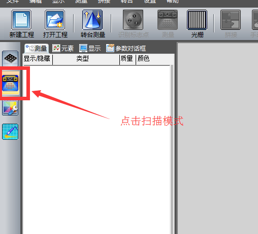
1) Enter scan mode

2) New construction


Note: There are three options in the new project: the single-chip measurement project refers to scanning once and does not require splicing; splicing measurement project refers to taking multiple photos of data from different angles and finally splicing the data; The draft measure refers to the non-collection of physical surface data (point cloud data) and is only responsible for mobile phone checkpoints.
Under normal circumstances, we choose the second type of “splicing measurement project”

Note: You can choose the project name yourself and save the location.
2. Identify landmarks

Note: When the new project is completed, the screen automatically switches to the marker point identification interface. Observe the images from the left and right cameras on the right. You can see there are green dots in the image. Identification of marker points is complete. If there is no green dot, it means the recognition failed and you need to go back to the calibration step for calibration.
2. Change system settings
1) Enter the setting interface


Note: Mainly set these two settings (other settings can be set by default). The defined parameters are not absolute and can be changed at any time depending on the situation.
2) Collection

Just use full resolution so the collection effect will be better

It can be turned on when scanning very bright objects, but it is recommended to turn it off at ordinary times.

After verification, the collection is completed and the noise points are automatically processed.
3) Splicing


Note: Global splicing refers to the final splicing after all multi-angle acquisitions are completed at the same time; Single splicing mode refers to collecting data once and splicing it once. It is recommended to choose the overall splicing model, which is relatively efficient.
4) Click OK once the setting is complete.
3. Measurement (data collection)
1) Make sure the object we are scanning is within the scanning range


2) After confirmation, click “Measure”


Note: Brightness changes will occur during the acquisition process and network adjustment bands will appear.

Note: After the collection is completed, the point cloud data collected once will be displayed in the middle.
3) Take the second measurement


Note: Measure (collect) data from multiple angles by moving physical objects at different angles.

Note: In the data collection area, use commands such as selecting the point cloud data in the middle, zooming in and out with the mouse wheel, and moving the data with SHIFT + right mouse button to observe the gaps.

Note: Look at the collection list on the left. Green represents the data collected this time and gray represents the angle data collected previously.

Note: If a red error number is displayed, it means there is a problem with the collected data and it needs to be deleted and collected again.

Note: The above operation method collects different data from multiple angles to complete the final data collection.


Note: Data is collected by placing the scanned objects at different angles until collection is complete.
1) Collection completed


Note: Once splicing is complete, all data will turn gray, indicating success.
2) Export the file


Note: ASC means point cloud data file, STL means triangle patch data file, save it according to your own needs. You can also exit directly without saving, because the software has an automatic save command, you just need to open it in the project file, as shown in the figure

Note: Find the project file you need to open and open it to continue scanning.
3. Summary of measures (data collection):
This section mainly explains how to use a scanner to collect data. Clicking the “Measure” command to collect physical data from different angles, change the angle once collected (look for parts that are not displayed in the 3D software and are not collected for collection). ) until the collection is finally completed (it is inevitable that wrong data is collected or the software crashes during the collection process. If the first case happens, you can choose to delete some orders. If the second happens, simply find and open the project and continue scanning). Finally, the automatic point cloud data processing steps are completed by splicing, and finally the collected data is saved to the file in the format you need (stl, asc).
Daguang focuses on providing solutions such as precision CNC machining services (3-axis, 4-axis, 5-axis machining), CNC milling, 3D printing and rapid prototyping services.


