1 preface
When finishing large parts, manual alignment and measurement depend mainly on the operator’s skill level. If the part is moved to a three -dimensional measurement machine for inspection during the process, the precision of the treatment and the efficiency of the production will be affected. Aiming a series of problems existing in the finishing of large parts, this article designs an online measurement system for machine-tool. The online machine-tool measurement system automatically corrects the offset value to make a part of the process during the process, provides information feedback, reduces the influence of uncertain factors, improves the accuracy of positioning and processing of parts and reduces the auxiliary production time.[1]。
2 Principle of operating the online measurement system of combined machine tools
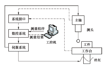
When the online measurement system of the combined machine-tool works, it is first important the CAD model of the part, selects the detection points, generates the detection program, then performs simulation verification. When verification of the simulation is correct, the industrial computer transmits the detection program to the CNC system via the communication machine communication interface, and the enslavement system leads to the probe to move according to the detection path . When the probe comes into contact with the part, a trigger signal is issued. The reception system receives the signal and then transmits it to the converter. The converter processes the signal and transmits it to the combined control system of the machine tool. The coordinates of the measurement point are recorded.[2]Then measure the following point and repeat the process above. Once all the points measured, the coordinates of the measurement points are transmitted to the industrial computer via the communication interface. The industrial computer performs subsequent processing on detection data and generates a detection ratio, as shown in Figure 1.
Figure 1 Operating principle of the online measurement system of combined machine tools
3 software design of an online measurement system for combined machine tools
The combined machine-tool measurement system software includes a measurement module, a data processing module, a posture adjustment simulation module, a data management module, an interface management module , a system configuration module and a maintenance/diagnostic module.
(1) Measuring module The measurement module is mainly used to connect the laser tracker, define the relevant measurement parameters, calibrate and measure to obtain the target point coordinates.
(2) Data processing module The data processing module is at the heart of the whole software. It can calculate the initial attitude and target attitude of the part according to the laser tracking measurement data, and carry out the conversion and unification of the coordinate system, as well as the margins inspection. and error analysis, as well as transformation and installation algorithms.
(3) Posture adjustment module The posture adjustment simulation simulation module includes offline simulation and real -time simulation of the posture adjustment process. Offline simulation is mainly used to check the accuracy of the posture adjustment trajectory in order to avoid interference. At the same time, it can estimate the time of adjustment of the posture on the basis of the dynamic model of the mechanism and the adjustment parts of the posture, so as to organize the posture reasonably. adjustment and treatment procedures. Real-time simulation, that is to say online simulation, must collect the coordinates of the key points in real time during the posture adjustment process and calculate its posture in real time for a display Updated, which can make the visual posture adjustment process. And easier to control.
(4) Data management module The data management module can manage various data involved in the posture adjustment process, in particular laser tracker measurement data, positioner coordinates and engine operating settings.
(5) Interface management module The interface management module is used to manage other interfaces of software software and hardware peripherals, in particular communication interfaces with laser trackers, communication interfaces with systems movement control (CNC systems) and data transfer/documents to the factory. Exit interface for the IT and other automation equipment of the station.
(6) The system configuration module defines the adjustment tolerance configuration, user/access configuration and other configurations according to real needs.
(7) The combined machine-tool of the maintenance/diagnostic module emits an alarm and the diagnostic module emits an alarm journal to diagnose mechanical components (circuit breakers, etc.).
4 material components of the online measurement system combined with machine tools
The online measurement system of the combined machine-tool uses a hazardous and a horizontal milling machine equipped with a CNC Siemens 840DSolution Line system as an execution device. Under the Windows XP professional operating system, Visual Studio 2008 and OpenGL 4.1 are used as secondary development tools. That the tool-tool can automatically perform the following task: check the accuracy of the posture adjustment trajectory, so as to reasonably organize the adjustment and posture processing procedures. Use the flipper on machine to find the part position, compile the measurement program on machine and assess the extra thickness, execute the measurement program on machine, analyze the measurement data and calculate the machining exhaust, compile the program D ‘Machining, execute the machining program and carry out the final inspection of the parts. To assess the quality of the treatment, if the treatment requirements of the treatment are met, the processing will be completed and the part will be withdrawn from the shelf if the treatment requirements of the treatment cannot be satisfied; An error analysis will be carried out. The material composition of the online measurement system of the tool-tool is as follows.
(1) Horizontal stretch and horizontal strawberry the cup functions of the rale and horizontal milling machine with three coordinates are milling, drilling and bore. Its operating principle is the rotation of the strawberry at the end of the spindle as a main movement, and. The lateral movement of the workbench (axis x). For the advance movement, the milling process is over. The drilling and bore of connection holes are carried out thanks to the rotation movement of the tool at the end of the spindle as the main movement and the longitudinal advance movement of the spindle supply axis (axis axis Z). Each axis of the machine tool is driven by a servomotor and the machine-tool guide rail uses linear guidance (the X axis uses linear roller guidance). In order to improve the rigidity and precision of positioning of the screw, the screw support for the pair of ball screws uses a set of ball bearings with oblique contact. The screw can be effectively pre-stretched during assembly. The lubrication device adopts centralized synchronization and a quantitative oil supply, and is equipped with a lubricating oil collection channel. Pin transmission, pin bearings and reducers are all cooled by circulation of cooling oil to control the increase in the spindle temperature and ensure that the spindle can maintain high operating accuracy.
(2) CNC system The machine tool adopts the CNC Siemens 840D Solution Line. The interface between the drive and the CNC is digital. The men-machine interface is based on Flex0s. All closed loop control software and hardware is integrated to facilitate surveillance. , program and exploit. The security function is performed via the SPL logical security program. At the same time, the second encoder (network ruler, etc.) or the manner of the servomotor is used as a safety encoder to complete the monitoring of the connection of the circuit of the enslavement device and. Machine measurement of the combined machine-tool.
(3) SERVO SYSTEM The Servo system (servomécanisme), also known as the Servo system, allows the mechanical output (or angle) displacement to accurately monitor the displacement (or angle) of input in order to to make a servocomande of the power position of the CNC machine tools and the spindle. Speeding the speed (or position).[3]system.
(4) Measuring system The measurement system consists of an optical probe, a signal transmission system and a data acquisition system. The Renishaw OMP60 probe uses a modulated optical transmission and has a long transmission distance. The OMI-2 optical receiver has a strong resistance to light interference and can be installed in the processing area of a horizontal stretch and milling machine to facilitate the sending and reception of probe signals and carrying out communication between the industrial computer and the probe. This is carried out by defining the relevant functions.
Once the communication connection has been established, the parameters linked to the measurement, such as environmental parameters, measurement methods and data collection frequency (see Figure 2), etc., are defined according to processing requirements.

Figure 2 Data collection
5 simulation function
The simulation module can read the design model directly, including the machine tool model, the attitude adjustment mechanism model and the parts model. Simulation collision control is illustrated in Figure 3. The model being relatively voluminous, in order to increase the reading speed and improve the fluidity of the simulation, the simulation module supports compression of the source file without Distortion, considerably reducing the space required on the hard drive and memory. The execution simulation function is implemented on the basis of the general VCH2020 machine tool simulation platform. The nucleus is written in C ++ and has the advantages of a rapid execution speed, low use of memory, high rendering efficiency and good lighting effect. VCH2020 provides a standard OpenGL display environment based on MFC, which can be used as a 3D engine to perform virtual reality tasks such as entities display, lighting and 3D interaction.[4]。

Figure 3 Verification of collisions by simulation
6 Machine measurement function
The alignment and evaluation of the margins are supplemented by the compilation of a macro measurement program. The macro measurement program adopts a functional CNC programming mode to classify the same type of functionalities to be measured and uses variables to represent information such as features size, process parameters, etc.[5]. The online measurement trajectory of the part is illustrated in Figure 4.

Figure 4 Online measurement trajectory of the part
The program is G65 P9814 D60 F1000 M100 A6 S6 S6, measuring a round hole with a diameter of 60 mm, the speed measurement speed is 1000 mm/min, the measurement speed is 100 mm/min, The approach distance is 6 mm and the search distance is 100 mm/min. 6 mm.
The machine probe can be installed in the designed tool store. When it is necessary to perform measurement tasks on machine, it can make automatic tool changes, reduce manual interventions and improve the efficiency and accuracy of the online measurement of parts. in Figure 5.

Figure 5 Parts online measures
6conclusion
The combined online measurement system of machine tools can be used for the measurement during the process and the inspection of the first part, thus eliminating the need for expensive montages and the disadvantages of manual alignment and measurements. Improvement of productivity and flexibility in prize size, thereby reducing rebuilding rates.
Daguang focuses on providing solutions such as precision CNC machining services (3-axis, 4-axis, 5-axis machining), CNC milling, 3D printing and rapid prototyping services.


