Using the principle of inverted design, the body of the Porsche car model was used as the research object, and laser scanning was used to obtain point cloud data on the surface of the body;Use Geomagic Wrap software (formerly Studio) to remove isolated points and noise points in vitro, as well as splicing and aligning point clouds to point cloud data;Then, the software was used to reconstruct the surface from the point-line surface, and the continuity and smoothness of the surface were analyzed to obtain a good quality CAD model of the automobile body, as well as a study preliminary on the application of reverse engineering in body design was completed.
Reverse engineering (also known as reverse engineering) is a process of replicating product design technology, that is, reverse analysis and research of a target product to infer and derive processing flow, organizational structure, functional features and technical specifications of the product, as well as other designs. elements to create products with similar functions but not exactly the same. Reverse engineering applications span most industries, from automotive to aerospace, arts and sciences, to medical. At present, reverse engineering research at home and abroad mainly focuses on reversing the geometric shape, that is, reconstructing the physical shape of the product.GUJATmodel, called “physical reverse engineering”. The reverse engineering system mainly includes three aspects: scanning physical geometric shapes, establishing CAD models and manufacturing products.
Modern body design adopts traditional design methods. However, the shape and structure of the car are complex, and there are many curved surfaces. To fully express it using general mechanical drawings, it requires a lot of manpower and material resources, which is a considerable waste. time. However, when the reverse engineering design method was introduced into automobile body design, it modified the previous design concept, shortened the design and development cycle, and achieved a high-quality body structure. Reverse engineering research attracts more and more attention, and great progress has been made in the research of data processing, surface fitting, geometric feature recognition, and three-dimensional measuring machines. However, in practical applications, the whole process still cannot fully guarantee the smoothness of the surface.
Considering these characteristics, the key points of this study are: 1) surface data acquisition and subsequent data processing 2) reconstruction technology and surface quality inspection of vehicle body , etc.
1. Collecting and processing point cloud data
1.1 Point cloud data collection
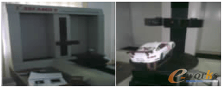
The point cloud data collection is shown in Figure 1.

Figure 1 Measuring equipment
In order to obtain good quality point cloud data, some preliminary processing is first done, such as determining the reference position of the model, spraying imaging solvent on the surface and software verification. The car model includes front, rear, upper, left and right sides. Since it cannot be measured at the same time, each surface must be measured separately. For the side, only one side should be measured. symmetrical product, the software can be used in mirroring. Figures 2 and 3 show the collected unprocessed vehicle body point cloud data.

Figure 2 Point cloud data from the side and top of the car body

Figure 3 Point cloud data of the front and rear of the body
1.2 Point cloud data processing
When measuring point clouds, some external factors will inevitably affect the quality of the point cloud, such as equipment vibration, temperature, humidity, etc. Additionally, the point cloud cannot be measured all at once. It must be divided into. several stages, and finally the different parts are assembled. It is necessary to process the point cloud before building the model. It is mainly divided into the following steps: removing isolated points and in vitro noise points, splicing and aligning point clouds. Geomagic Wrap software (original Studio) is used for processing, and the spliced vehicle point cloud is shown in Figure 4.

Figure 4 The entire vehicle after splicing
2. Reconstruction of the surface of a body model
In reverse engineering, there are two surface reconstruction methods: one consists of generating the surface directly from the point cloud; the other is to follow the point-line-area process. The first method requires that the quality of the point cloud data is good enough, so that the quality of the generated surface meets the requirements. It follows the points-polygon-surface steps and uses the Geomagic Wrap software (formerly Studio); The method is the traditional method. This method can process various point cloud data, and the accuracy of the obtained surface is also very high. This article mainly adopts the second method. Data processing mainly includes the following three processes: point cloud data processing, curve processing and surface processing. Since the point cloud data was processed in Geomagic Wrap (formerly Studio), the next two steps can be done directly.
2.1 The point cloud directly generates the surface
The so-called direct generation of curved surfaces means that curved surfaces can be generated by processing point clouds without the need for line construction. The directly generated NURBS surface can be directly imported into the CAD system for further processing and can be output in many formats, such as IGES, STEP, etc. Figure 5 shows the generated NURBS surface.

Figure 5 NURBS surface
2.2 The process of reconstructing from points, lines and surfaces
The point-line-surface process mainly uses 3D curves and 3-point arcs to construct curves, and then uses commands such as sweep, bridge, and round to process the surface.
1) Create body curves.Since the car body is a symmetric model, part of the point cloud needs to be intercepted before creating the curve, and finally the complete vehicle model is obtained by mirroring. Creating a curve involves intercepting part of the point cloud based on the existing point cloud, then generating a curve from the intercepted point cloud and finally adjusting the control points of the curve to control the accuracy to minimize the error between this and the point. cloud. The generated curve should be as simple as possible and can reflect the general shape of the surface, to ensure that the reconstructed surface has sufficient smoothness and the error is small. Figure 6 shows the intercepted point cloud on the vehicle body side and the line formed by the intercepted point cloud.

Figure 6 The intercepted point cloud and the formed line
2) Create the surface of the body.When creating a surface, smoothness and precision cannot be achieved at the same time. You can only choose one or the other. In order to control the error, adjustment control points are usually used to control the distance between the surface and the original point cloud. This method is generally adjusted manually, so there is a certain error, but it can basically meet industrial requirements. Figure 7 shows the vehicle body side checkpoint model, and Figure 8 shows the error between the reconstructed vehicle body side surface and the original point cloud.

Figure 7 Vehicle body side checkpoints

Figure 8 Error between body side and original point cloud
It can be seen from Figure 8 that the original point cloud (blue area) and the reconstructed surface (red area) on the body side are relatively evenly distributed, so the error between the surface and the cloud points can be pretty much assured. If a large red or blue area appears, it means that the reconstructed surface has a significant error compared to the original point cloud and cannot meet the requirements. This method involves controlling the error by adjusting the control points. The reverse body design of this article mainly uses this method. Figure 9 shows the curved surfaces of the hood and top of the body reconstructed using this method.

9-shaped hood and upper body
2.3 Treatment between different surfaces
After each part of the surface is created, operations such as rounding, trimming, bridging and stitching must be performed on the surface to achieve a continuous surface. Rounding is a basic processing method between curved surfaces. The rounded transition not only avoids stress concentration and improves strength, but also directly affects the aesthetics of the product. Figure 10 shows the before and after effects of rounding the curved surfaces at the rear of the car.

Figure 10 Before and after effects of rounding the rear curved surface of the car

Figure 11 Vehicle body model
3 Body surface quality assessment
3.1 Surface continuity analysis
For bodywork, continuity means a uniform transition of curvature between curved surfaces and the absence of dead spots. Surface continuity roughly includes the following four aspects: position continuity (G0), tangent continuity (G1), curvature continuity (G2), and curvature tangent continuity (G3). Under normal circumstances, as long as the tangent line is continuous, it can basically meet industrial needs. There is a term in the automotive industry: A-face. The so-called A-surface refers to a surface that must meet the requirements that the gap between adjacent curved surfaces is less than 0.005 mm, the change in shear rate is less than 0.16° and the change in curvature is less than 0.005°. Generally, the continuity of a surface can be judged using a curvature comb. The length and direction of adjacent curvature pins of the curvature comb reflect the curvature value and curvature direction of the surface. Check the curvature comb in U and V directions to get the analysis results of the rear and front of the car, as shown in Figure 12.

Figure 12 Continuity analysis results at the rear and front of the car
Figure 12 shows that the continuity between the multiple curved surfaces at the rear and front of the car is good.
3.2 Surface smoothness analysis
The surface smoothness analysis criteria form the basis of smoothness analysis. The surface smoothness criterion is as follows: the lines U, V and other surface parameters are parallel to the intersection lines obtained by the intersection of two sets of equidistant planes in the U and V directions respectively. The smoothness of the surface can be judged. checking the intersection lines on the surface. For the analysis of the smoothness of the produced surface, there are mainly detection methods such as curvature combs and highlighting reflection lines in the U and V directions.
The highlight line analysis method can visually check the smoothness of the surface. The smoothness of the surface can be judged by observing the uniformity of the lines. The more uniform the smoothness of the surface, the better. It is a set of reflections obtained by projecting a set of parallel light sources onto a curved surface. Figures 13 and 14 show the smoothness inspection results of several main surfaces of the car body.

Figure 13 Distribution diagram of the front hood and body side reflection lines

Figure 14 Distribution diagram of the reflection lines of the rear roof and body panel
It can be seen that the distribution of reflection lines is relatively uniform, and the smoothness of the curved surface basically meets the requirements. Therefore, the reverse design generally meets the design requirements.
4. in conclusion
This paper conducts research on three-dimensional modeling design of automobile bodies based on reverse engineering technology. The main results of the research are: 1) Use of Geomagic. Wrap software (formerly Studio) processes the point cloud data measured with a 3D measuring instrument to obtain the spliced point cloud data of the entire vehicle body; the software is then used to reconstruct the surface of the line of points to obtain completeness; vehicle body point cloud data. Car body surface model; 2) Carry out continuity and smoothness analysis on the reconstructed vehicle body surface model, and finally obtain a body CAD model that meets the design requirements, which can be used later.Finite element analysisProvides the basis for optimization design and multi-body dynamic analysis.
From the current point of view, reverse engineering technology still has certain development bottlenecks, which has slowed down the development of reverse engineering. However, compared with forward design, reverse design has obvious advantages and can bring huge benefits to enterprises, so it has broad development prospects.
source:e-works site
Daguang focuses on providing solutions such as precision CNC machining services (3-axis, 4-axis, 5-axis machining), CNC milling, 3D printing and rapid prototyping services.


