
Custom ODM Metal 3D Printing: How Custom Metal Parts Get Made
This page explains the mechanics of custom ODM metal 3D printing and where it fits in a custom metal parts program. It is written for design and manufacturing engineers who need to judge whether printing, machining, or a mix of both is the right call for a given part.
In this article
- 1
- 2
- 3
- 4
- 5
- 6
- 7
Key takeaways
How Custom ODM Metal 3D Printing Actually Builds a Part
Custom ODM metal 3D printing is not one process. For production metal parts it usually means laser powder bed fusion, sold under names like DMLS or SLM. A recoater spreads a thin layer of metal powder, typically 20 to 60 μm, across the build plate. A laser melts a cross-section of the part into that layer. The plate drops by one layer thickness and the cycle repeats.
Heat is the whole story. The melt pool cools at rates in the range of 10^6 K/s, which produces a fine grain structure but also traps residual stress. That stress is why thin, tall, unsupported geometry can curl or crack during the build. It is also why the part often needs a stress-relief heat treatment before it is cut from the plate.
Material choice is narrower than in CNC. Common powders include 316L and 17-4PH stainless, Ti-6Al-4V, Inconel, and aluminum alloys such as AlSi10Mg. Each has its own laser parameters, and each powder batch has a particle size distribution that affects flowability. Reused powder changes the chemistry slightly, so a controlled powder management program matters more than most buyers expect.
The build is near-net, not net. As-built surfaces typically land around Ra 8–15 μm, and dimensional spread on a well-oriented feature might be ±0.1 mm or looser. Anything tighter than that goes to a CNC after the build. That is the normal workflow, not an admission of failure.
- 1Layer thickness20–60 μm is the usual band; thinner layers cost more build time.
- 2Melt pool coolingFast cooling gives fine grains and high residual stress.
- 3Powder reuseTrack chemistry and oxygen content, not just sieve size.
- 4As-built surfacePlan for Ra 8–15 μm before any finishing step.
Design Rules That Decide Whether a Part Prints Well
Orientation is the first decision, and it drives everything else. A part built flat on the plate needs less support but may have worse surface finish on the top face. A part built upright saves support material but stacks more layers, which means more build time and more residual stress. There is no universal answer, so we usually try two orientations and compare support volume against surface requirements.
Overhangs are the second constraint. Surfaces that face downward at more than about 45° from vertical need support. Support is not free: it adds build time, it leaves witness marks, and on internal channels it can be nearly impossible to remove. A design with a long horizontal internal bore is a classic case where the print succeeds and the cleanup fails.
Wall thickness has a practical floor. Below roughly 0.4 mm, thin walls become sensitive to thermal distortion and to the recoater blade. Yields drop and the part may pass inspection on one build and fail on the next. If a design needs 0.3 mm walls for weight reasons, we would rather machine that feature or accept a slightly thicker wall than gamble on repeatability.
Trapped powder is the failure mode that surprises people. Any enclosed hollow volume needs a drain path, or powder stays inside the part forever. A 3 mm drain hole at the lowest point of each cavity solves it. We also check that the hole does not sit on a sealing face.
- 1Orientation trialCompare support volume against required surface finish.
- 2Overhang limitPast about 45° from vertical, plan for support.
- 3Wall thicknessKeep load-bearing walls at 0.4 mm or thicker.
- 4Drain holes3 mm minimum at the low point of every cavity.
Why Post-Machining Is Where the Tolerance Comes From
A printed part off the plate is a blank. It has the right shape and roughly the right mass, but the interfaces that matter, bores, sealing faces, bearing seats, threads, and dowel holes, are not yet at tolerance. This is where the process chain continues into CNC.
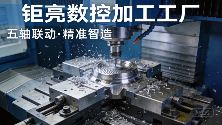
On our floor that means a printed blank can move straight to a 5-axis machining center for datum establishment and finishing. We hold ±0.005 mm on critical features and can reach Ra 0.2–0.8 μm on a lapped or fine-bored face. The printed material machines differently from wrought stock, so feeds and speeds are adjusted for the finer, more uniform grain.
Heat treatment usually sits between the two. Stress relief after the build and before plate cutting keeps the part from moving during machining. For titanium and Inconel, a hot isostatic press step can close internal porosity, which matters for fatigue-loaded parts. That step is specified per application, not applied by default.
Support removal, powder evacuation, and surface finishing round out the chain. Bead blasting brings an as-built surface to a uniform matte. Anodizing, electroless nickel, or black oxide can follow if the part needs corrosion resistance or a specific appearance. Laser marking is available down to 1.5 mm character height for traceability.
- 1Datum firstEstablish datums on the printed blank before finishing.
- 2Critical facesMachine to ±0.005 mm; finish to Ra 0.2–0.8 μm when needed.
- 3Stress reliefRun before plate cutting to limit distortion.
- 4FinishingBead blasting, anodizing, plating, laser marking as required.
When to Choose Custom ODM Metal 3D Printing Over CNC
Printing wins when geometry is the problem. Internal channels that cannot be reached by a cutter, lattice structures that save mass, conformal cooling paths in a mold insert, or a single-piece bracket that would otherwise be welded from five parts. If a machinist looks at the drawing and asks how the tool gets in there, that is a print candidate.
CNC wins when tolerance and surface are the problem. A part with a 20 mm bore at H7, a flat sealing face, or a thread callout is usually cheaper and faster as a machined part. Printing it and then machining those features adds steps without adding value. For simple prismatic geometry, subtractive is still the default.
Volume changes the math. Printing has no tooling cost, so one to a few hundred units is comfortable. Above that, die casting or machining from bar can pull ahead on unit cost. Our runs go from a single prototype to 10,000+ parts, and we will say plainly when a print is not the economic choice.
Lead time is often the deciding factor. Quotation and free DFM analysis come back within 12 hours, production can start within 24 hours, and parts ship in 3–5 days. That window is hard to match with a tooling-based process, and it is usually why a program starts with a print even when the final part will be cast or machined.
- 1Choose printingInternal channels, lattices, consolidated assemblies, low volume.
- 2Choose CNCTight bores, threads, sealing faces, simple prismatic shapes.
- 3Volume shiftPast a few hundred units, compare against casting.
- 4Lead time12-hour quote, 24-hour start, 3–5 day shipment.
Inspection, Certifications, and What Gets Documented
Printed metal has two quality fronts: the build and the machining. On the build side, layer documentation, powder batch records, and parameter logs tell you what actually happened. On the machining side, a coordinate measuring machine report confirms the features you specified. We inspect 100% of parts before shipment, covering raw material check, in-process monitoring, and final inspection.
Reports are available on request, and for regulated programs they are not optional. GreatLight holds ISO 9001:2015 for quality management, IATF 16949:2016 for automotive components, ISO 13485:2016 for medical hardware, and ISO 27001:2022 for information security. Those last two matter when the part is an implant prototype or when the drawing itself is sensitive.
Confidentiality is part of the process for ODM work, since you are handing over a design that does not exist anywhere else yet. Uploads are handled as confidential, and a non-disclosure agreement is available on request before any file moves.
The honest limit: no inspection plan can prove a printed part is free of internal porosity without destructive testing or a CT scan. For fatigue-critical parts, we specify HIP and then verify with a coupon built in the same job. That is the only way to tie material properties to the actual build.
- 1Build recordsLayer documentation, powder batch, parameter logs.
- 2CMM reportsFeature verification against the drawing.
- 3CertificationsISO 9001, IATF 16949, ISO 13485, ISO 27001.
- 4PorosityCoupon testing or CT scan for fatigue-critical parts.
Printed Blank vs Machined Part vs Hybrid
Use this when the drawing has mixed requirements.
| Requirement | Printed blank | CNC from bar | Hybrid print + CNC |
|---|---|---|---|
| Internal channels | Yes, with drain paths | Limited by tool access | Yes, then machine ports |
| Tolerance on bores | ±0.1 mm as-built | ±0.005 mm | ±0.005 mm after finishing |
| Surface finish | Ra 8–15 μm as-built | Ra 0.8–1.6 μm typical | Ra 0.2–0.8 μm on critical faces |
| Tooling cost | None | Fixtures only | None |
| Best volume band | 1 to a few hundred | 1 to 10,000+ | 1 to a few thousand |
| Typical lead time | 3–5 days | 3–5 days | 5–8 days |
| Best for | Organic, consolidated shapes | Prismatic, tight-tolerance parts | Functional parts with interfaces |
The clear call
If the part is defined by internal geometry that no cutter can reach, print it and machine the interfaces. If the part is defined by a bore, a thread, or a sealing face, machine it from bar and skip the print. Mixed requirements go hybrid, not all-printed.
Questions engineers ask before the first build
What is the smallest feature a metal print can hold reliably?
Feature size depends on layer thickness and laser spot size. As a working rule, keep walls at 0.4 mm or thicker and holes at 1 mm or larger if you need a repeatable result.
Smaller features can be built, but yield drops and the part may pass on one build and fail on the next. If the feature is functional, machine it instead.
Can a printed part be threaded?
Threads can be printed, but the flanks come out rough and the pitch diameter is hard to hold. For anything that takes load or seals, we print a pilot hole and cut the thread on a CNC.
Printed threads are acceptable for light-duty, low-cycle applications where a slightly loose fit is fine.
How does powder reuse affect part quality?
Reused powder picks up oxygen and its particle size distribution shifts as fines are consumed. That changes flowability and melt behavior.
A controlled program tracks chemistry and oxygen content per batch rather than sieving alone. Without that, two builds from the same file can differ in density.
Do I need HIP for every printed part?
No. HIP closes internal porosity and improves fatigue life, but it adds cost and a process step. It is specified for fatigue-loaded or safety-critical parts, not for brackets and covers.
For most prototypes and fixtures, stress relief is enough.
What file format and information do you need for a quote?
A STEP file is preferred over STL, because STEP carries the solid geometry rather than a triangle mesh. Include the material, the tolerances on critical features, and any surface finish callout.
Quotation and free DFM analysis come back within 12 hours, and production can start within 24 hours after approval.
Is there a minimum order quantity?
No minimum order quantity. We run from a single prototype to 10,000+ part runs.
For ODM programs that start with one build and scale later, the same process and inspection plan carries over.
Send the drawing, get a DFM review in 12 hours
Upload a STEP file and we will come back with a quotation, a printability check, and a note on which features should be machined instead of printed.
12-hour quote and DFMNo minimum order quantity100% inspection before shipmentNDA available on request
More from the shop floor
We publish setup notes, tooling trials and inspection data from the factory floor.











