Click to learn more about real-time 3D modeling from Mohou.com
Today, Mohou.com will briefly learn the five basic operations of 3D modeling software DesignX with you.
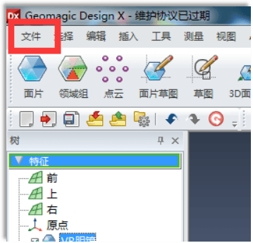
1.Put the scanned data (asc、slutetc.) import software

The drop down menu below includes allDesignXAre there supported data formats? Only valid data formats will be displayed in the drop-down menu. InstalledDesignXIn the future, the system will come with some folders. Thumbnail images of any file can be created using “File–Open the dialog box preview function to view.
It should be noted that displaying the open dialog box is onlyDesignXThe file format that the software can open by default and some data can be dragged directly into itDesignXPerforming operations indoors, for example (stl,ascwait)

2.Align the coordinate system
Aligning the coordinate system is the first step after importing engineering data, because the coordinate system of the data itself and the world coordinate system are offset by default after importing a lot of data into the software. At this point, we need to align the coordinate system of the data itself with the spatial coordinate system (i.e. world coordinate system) in the software through operations such as lines, points, surfaces and physical objects. Aligning the coordinate system is the most important point of the entire reverse process, because many people make mistakes when adjusting the coordinate system early, which will cause many later commands to fail to work. The most fatal thing is that the error does not occur. the required precision.

As picture showsIn addition to the imported factory data, twozxThe surface is the world coordinate system.

Click “Manual Alignment” in the lower center control box

Click the right arrow button

As picture showsThere are two alignment methods after entering the interface:3-2-1、XYZ. Choose normally3-2-1Simply select a face and the opposite face of that face (pay attention to the top, bottom, left and right symmetry when selecting, otherwise there will always be errors after alignment)

As picture showsis the effect after alignment (XZBoth surfaces are aligned with the data coordinates)
3.Split domain groups
The domain group isDXThis is a relatively essential command. The field group, as its name suggests, consists of dividing a piece of data into several different fields via this command, in order to perform editing operations on different fields. As shown in the figure above, inDXDifferent colors represent different zones, and the zones can be divided by yourself or automatically.

After clicking on the domain group command, the automatic segmentation command box will appear automatically. It should be noted that the greater the sensitivity, the greater the sensitivity of collecting the data surface. Therefore, for some engineering data with simple and non-complex surface objects. structure, sensitivity must be controlled within20-40Roughly.

4.patch fitting

After clicking patch adjustment, a patch adjustment operation box will automatically appear as shown in the figure. You can select the resolution checkpoints or allowed deviation based on your needs. patch fittingDXA relatively central software control directly adjusts a portion of the fields based on previously divided field groups to form the required slice body.

Slice body mounted using one-sided mounting
5.Detect gaps

Click the gap and the change effect is as follows

The green part indicates that the gap between the adjusted slice and the imported technical data is within the acceptable range, the yellow gap is slightly larger, and the red part indicates that it is not adjusted at all.
Daguang focuses on providing solutions such as precision CNC machining services (3-axis, 4-axis, 5-axis machining), CNC milling, 3D printing and rapid prototyping services.


