Blender 3D modeling software: How to add vertices?

blender 3d modeling software: how to add vertices?

existIn 3D modeling, a vertex is a single point in three-dimensional space. A single vertex has three coordinates: the values ​​of the X, Y and Z axes. Adding vertices improvesThe detail and control of 3D models is crucial. For example, if you’re optimizing an existing project, placing vertices on edges or faces can result in […]

CNC Content Navigation

existIn 3D modeling, a vertex is a single point in three-dimensional space. A single vertex has three coordinates: the values ​​of the X, Y and Z axes.

Adding vertices improvesThe detail and control of 3D models is crucial. For example, if you’re optimizing an existing project, placing vertices on edges or faces can result in more precise sculpting, especially in complex areas. After adding vertices, you can use them to seamlessly connect objects or edges, resulting in clean geometry, which is crucial for high-quality modeling or to avoid issues when modeling. 3D printing.

However, you should be careful when adding vertices, as overly detailed geometry can overcomplicate the object and even lead to non-multiple edges and floating vertices. If you are modeling for animation, you may want four vertices per face, as this makes it easier to deform during movement.

existThere are several techniques for adding vertices in Blender, each serving a unique purpose. Next, we’ll look at some options related to adding vertices.

A,Ctrl+right click

Blender 3D modeling software How to add vertices

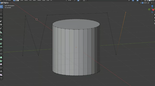
Create and link vertices by edges on the cylinder (Source:Ofonime William via All3DP)

also known asThe “right click add” method is the easiest and fastest way to add vertices in Blender. Here’s how to do it:

1. Import (or create) your model first.

2、according toThe “Tab” key allows you to switch from “Object” mode to “Edit” mode.

3、Press and hold“Ctrl” key and right-click in the direction you want to place the vertex.

If an edge or vertex is highlighted (selected), then when you press and holdThe “Ctrl” key and right click will create a new vertex connected to this vertex by an edge.

two,Segmentation

1733661782 908 Blender 3D modeling software How to add vertices

Cone with subdivided edges resulting in multiple vertices (source:Ofonime William via All3DP)

also known asThe “Add Vertices to Edges” method, which allows you to add more details to a part. It allows you to manipulate geometry into more precise shapes.

Here’s how to add vertices by subdividing edges:

1、Again, place the object in the workspace and pressThe “Tab” key (red) switches to “Edit” mode.

2、move on to“Edge Selection” (yellow, second option) and select the edges you want to subdivide.

3、right clickanywhere in the 3D view to open the vertex context menu.

4、choose“Segmentation”.

5、existIn the lower left corner of the 3D view, a control panel (green) will appear. Here you can change the number of vertices added; this will split the edges based on the number of vertices, adjusting smoothness and other variables. This method also works with faces (another type of object).

Note that this creates vertices at the ends (ends) of the subdivision edges, you will need to return to“Vertex Selection” mode (yellow) to find newly added vertices.

three,Merge edges with vertices

1733661783 655 Blender 3D modeling software How to add vertices

Vertex Slide applied to the top edge of the box (Source: Ofonime William via All3DP)

Discontinuous geometry within a single object can lead to complex problems, including non-multiple geometry,n-gons and strange artifacts. You can connect meshes using Boolean operations, but this can sometimes lead to unexpected results. Edge blending is more precise by adding and merging vertices at specific locations, like this:

1. Use the subdivision method we learned in the previous section to add vertices near the contact points.

2、to useThe Vertex Slide (Shift+V) function positions the new vertex as close to the contact point as possible. It will slide in the direction of mouse movement and can be held in place with a left click.

3、Select a vertex and holdShift and select another vertex. Press the “M” key to use the merge function, then select how you want to merge the vertices from the available options.

Please note that“n-gons” is short for polygons with more than four sides, such as a hexagon (six sides) or any other shape with “n” sides. They are useful for modeling complex shapes, but can cause problems with animation and 3D rendering, especially when subdividing or deforming the model. The higher the number of edges, the more unpredictable the results, which can be particularly problematic if you plan to 3D print the model.

Four,Add-on “Additional objects”

1733661783 938 Blender 3D modeling software How to add vertices

Install the plugin locally (source:Ofonime William via All3DP)

You can useThe “Extra Object” method adds a single vertex as a new object. If you are using a version of Blender earlier than 4.1, you will need to install the Extra Mesh Objects and Extra Curve Objects add-ons. There are several ways to do this; Let’s look at one of the simplest:

1、To install the plugin locally, you need the installation files. You can modify it directly fromBlender extensions are downloaded to the local device (desktop).

2、Go toGo to Blender’s Edit menu and select Preferences.

3、scroll to“Add-ons” you can search for all available add-ons to customize your version of Blender. In the upper right corner, select “Install…” to install the add-on you just downloaded.

4. Navigate in the window to find and select the add-on.

5、After installation, make sureThe Additional Mesh Objects and Additional Curve Objects boxes are checked. Close the menu.

Or if yourStarting with Blender version 4.1, these steps are no longer required because the add-on is now part of the setup. However, you need to enable them by going to Edit > Preferences > Add-ons and checking “Add Curves: Additional Objects” and “Add Mesh: Additional Objects”.

now, inIn Object mode, you can select Add (or Shift+A) and navigate to Mesh > Single Vertex > Add Single Vertex. By default, this adds a vertex to the origin, but you can change the target position using the submenu options.

five,Alternative method

1733661783 274 Blender 3D modeling software How to add vertices

Vertices generated using the cut tool based on the cut path (yellow) (Source:Ofonime William via All3DP)

These are secondary (less commonly used) methods that create vertices immediately or by making them easier to create and manipulate. Let’s see what they are.

1、Knife tools: inIn “Edit” mode, this will add vertices in a controlled manner, depending on the path traveled by the tool (yellow). Note that this will introduce some edges. The image above shows the vertices added next to the edge, representing the part where the cutting tool (red) is placed.

2、Poke Faces: This feature works best with faces, allowing the addition of vertices and certain edges that can be exploded or removed. existIn Edit mode, switch to Face Selection and click the face you want to add vertices to, right-click the face and select Face Stamp from the options. As mentioned before, this will be a peak in the center of the face.

3、Extrude: inIn “Edit” mode, select “Vertex Selection”, select the desired vertex and press command “E” to extrude it (a new vertex will be created). If you select two vertices that form an edge, command “E” will extrude a face.

4、Auto-merge vertices: This method collapses vertices to a single vertex. existIn Edit mode, from the Properties menu on the right side of the workspace, select Tool Settings (starting at the top). Expand Options, enable Auto Merge, and change the Threshold to 0. Then select the vertices you want to merge, click the “S” and move your mouse in the direction you want the merged vertices to appear, then click on them with the left button.

Daguang focuses on providing solutions such as precision CNC machining services (3-axis, 4-axis, 5-axis machining), CNC milling, 3D printing and rapid prototyping services.

CNC Experts

Picture of JinShui Chen

JinShui Chen

Rapid Prototyping & Rapid Manufacturing Expert

Specialize in CNC machining, 3D printing, urethane casting, rapid tooling, injection molding, metal casting, sheet metal and extrusion

CNC Recent Posts

CNC News

Common CNC Machining Products

Welcome to GreatLight Metal,Maximum Processing Size 4,000 mm

Precision Machining CNC Quote Online

Loading file

Upload Click here to upload or drag and drop your model to the canvas.

The model is too large and has been resized to fit in the printer's build tray. [Hide]

The model is too large to fit in the printer's build tray. [Hide]

The model is too large, a fitting printer is selected. [Hide]

The model is too small and has been upscaled. [Hide]

Warning: The selected printer can not print in full color [Hide]

Warning: obj models with multiple meshes are not yet supported [Hide]

Warning: Unsupported DXF entity  [Hide]

Warning: could not arrange models [Hide]


File Unit:      
Scale:
%
L × W × H:
X: × Y: × Z:  cm 
Rotation:
X: ° Y: °  

	
⚡ Instant Quote for Precision Manufacturing

Submit your design files (STEP/IGES/DWG) and receive a competitive quote within 1 hour, backed by ISO 9001-certified quality assurance.

📋 How It Works

  1. Upload & SpecifyShare your 3D model and select materials (Aluminum/Stainless Steel/Titanium/PEEK), tolerances (±0.002mm), and surface treatments.

  2. AI-Powered AnalysisOur system calculates optimal machining strategy and cost based on 10+ years of automotive/aerospace data.

  3. Review & ConfirmGet a detailed breakdown including:
    - Volume pricing tiers (1-10,000+ units)
    - Lead time (3-7 days standard)
    - DFM feedback for cost optimization

Unit Price: 

Loading price
5 Axis CNC Machining Equipment
4 Axis CNC Machining Equipment
3 Axis CNC Machining Equipment
CNC Milling & Turning Equipment
Prototype and Short-Run Injection Moldings Exact plastic material as final design
Volume Metal Die Casting Services - Precision Cast Parts
Bridge the Gap From Prototype to Production – Global delivery in 10 days or less
Custom high-precision sheet metal prototypes and parts, as fast as 5 days.
Custom Online 3D Printing Services
Design Best Processing Method According To 3D Drawings
Alloys Aluminum 6061, 6061-T6 Aluminum 2024 Aluminum 5052 Aluminum 5083 Aluminum 6063 Aluminum 6082 Aluminum 7075, 7075-T6 Aluminum ADC12 (A380)
Alloys Brass C27400 Brass C28000 Brass C36000
Alloys Stainless Steel SUS201 Stainless Steel SUS303 Stainless Steel SUS 304 Stainless Steel SUS316 Stainless Steel SUS316L Stainless Steel SUS420 Stainless Steel SUS430 Stainless Steel SUS431 Stainless Steel SUS440C Stainless Steel SUS630/17-4PH Stainless Steel AISI 304
Inconel718
Carbon Fiber
Tool Steel
Mold Steel
Alloys Titanium Alloy TA1 Titanium Alloy TA2 Titanium Alloy TC4/Ti-6Al 4V
Alloys Steel 1018, 1020, 1025, 1045, 1215, 4130, 4140, 4340, 5140, A36 Die steel Alloy steel Chisel tool steel Spring steel High speed steel Cold rolled steel Bearing steel SPCC
Alloys Copper C101(T2) Copper C103(T1) Copper C103(TU2) Copper C110(TU0) Beryllium Copper
Alloys Magnesium Alloy AZ31B Magnesium Alloy AZ91D
Low Carbon Steel
Alloys Magnesium Alloy AZ31B Magnesium Alloy AZ91D
ABS Beige(Natural) ABS Black ABS Black Antistatic ABS Milky White ABS+PC Black ABS+PC White
PC Black PC Transparent PC White PC Yellowish White PC+GF30 Black
PMMA Black PMMA Transparent PMMA White
PA(Nylon) Blue PA6 (Nylon)+GF15 Black PA6 (Nylon)+GF30 Black PA66 (Nylon) Beige(Natural) PA66 (Nylon) Black
PE Black PE White
PEEK Beige(Natural) PEEK Black
PP Black PP White PP+GF30 Black
HDPE Black HDPE White
HIPS Board White
LDPE White
This is a finish of applying powdered paint to the components and then baking it in an oven, which results in a stronger, more wear- and corrosion-resistant layer that is more durable than traditional painting methods.
No coating required, product’s natural color!
This is a finish of applying powdered paint to the components and then baking it in an oven, which results in a stronger, more wear- and corrosion-resistant layer that is more durable than traditional painting methods.
This finishing option with the shortest turnaround time. Parts have visible tool marks and potentially sharp edges and burrs, which can be removed upon request.
Sand blasting uses pressurized sand or other media to clean and texture the surface, creating a uniform, matte finish.
Polishing is the process of creating a smooth and shiny surface by rubbing it or by applying a chemical treatmen
A brushed finish creates a unidirectional satin texture, reducing the visibility of marks and scratches on the surface.
Anodizing increases corrosion resistance and wear properties, while allowing for color dyeing, ideal for aluminum parts.
Black oxide is a conversion coating that is used on steels to improve corrosion resistance and minimize light reflection.
Electroplating bonds a thin metal layer onto parts, improving wear resistance, corrosion resistance, and surface conductivity.
This is a finish of applying powdered paint to the components and then baking it in an oven, which results in a stronger, more wear- and corrosion-resistant layer that is more durable than traditional painting methods.
Please provide additional text description for other surface treatment requirements!
Material
Material
  • CNC Metals
    • Aluminum
    • Brass
    • Stainless steel
    • Inconel718
    • Carbon Fiber
    • Tool Steel
    • Mold Steel
    • Titanium
    • Alloy Steel
    • Copper
    • Bronze
    • Low Carbon Steel
    • Magnesium
  • CNC Plastics
    • ABS
    • PC
    • PMMA (Acrylic)
    • PA (Nylon)
    • PE
    • PEEK
    • PP
    • HDPE
    • HIPS
    • LDPE
Printer
Printer
  • CNC Metals
    • 5 Axis CNC Machining
    • 4 Axis CNC Machining
    • 3 Axis CNC Machining
    • CNC Milling & Turning
    • Rapid Tooling
    • Metal Die Casting
    • Vacuum Casting
    • Sheet Metal Fabrication
    • SLA 3D Printing
    • SLS 3D Printing
    • SLM 3D Printing
  • Rapid Prototyping
    • Design Best Processing Method According To 3D Drawings
Post-processing
Post-processing
Finalize
The world's first CNC machining center that dares to provide free samples!

Free for first product valued at less than $200. (Background check required)

precision machining cnc quote online

15 Years CNC Machining Services

When you’re ready to start your next project, simply upload your 3D CAD design files, and our engineers will get back to you with a quote as soon as possible.
Scroll to Top

ISO 9001 Certificate

ISO 9001 is defined as the internationally recognized standard for Quality Management Systems (QMS). It is by far the most mature quality framework in the world. More than 1 million certificates were issued to organizations in 178 countries. ISO 9001 sets standards not only for the quality management system, but also for the overall management system. It helps organizations achieve success by improving customer satisfaction, employee motivation, and continuous improvement. * The ISO certificate is issued in the name of FS.com LIMITED and applied to all the products sold on FS website.

greatlight metal iso 9001 certification successfully renewed
GB T 19001-2016 IS09001-2015
✅ iso 9001:2015
greatlight metal iso 9001 certification successfully renewed zh

ISO 13485 certificate

ISO 13485 is an internationally recognized standard for Quality Management Systems (QMS) specifically tailored for the medical device industry. It outlines the requirements for organizations involved in the design, development, production, installation, and servicing of medical devices, ensuring they consistently meet regulatory requirements and customer needs. Essentially, it's a framework for medical device companies to build and maintain robust QMS processes, ultimately enhancing patient safety and device quality.

greatlight metal technology co., ltd has obtained multiple certifications (3)
greatlight metal technology co., ltd has obtained multiple certifications (4)

ISO 27001 certificate

ISO/IEC 27001 is an international standard for managing and processing information security. This standard is jointly developed by the International Organization for Standardization (ISO) and the International Electrotechnical Commission (IEC). It sets out requirements for establishing, implementing, maintaining, and continually improving an information security management system (ISMS). Ensuring the confidentiality, integrity, and availability of organizational information assets, obtaining an ISO 27001 certificate means that the enterprise has passed the audit conducted by a certification body, proving that its information security management system has met the requirements of the international standard.

greatlight metal technology co., ltd has obtained multiple certifications (1)
greatlight metal technology co., ltd has obtained multiple certifications (2)

IATF 16949 certificate

IATF 16949 is an internationally recognized Quality Management System (QMS) standard specifically for the automotive industry. It builds upon the foundation of ISO 9001 and adds specific requirements relevant to automotive production and service parts. The goal is to enhance quality, improve processes, and reduce variation and waste within the automotive supply chain.

automotive industry quality management system certification 01
automotive industry quality management system certification 00

Get The Best Price

Send drawings and detailed requirements via Email:info@glcncmachining.com
Or Fill Out The Contact Form Below:

All uploads are secure and confidential.