This article systematically analyzes a new method for machining large arc surfaces on machines with four horizontal axes, establishes a mathematical model, writes a macro macro configuration, improves the efficiency of treatment of arc surfaces and ensures quality product processing.
1. Treatment and analysis
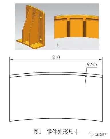
Arc surfaces are a common treatment characteristic and there are many treatment methods. The machining of large arc surfaces is always a difficult point in daily machining. As shown in Figure 1, the external dimensions are 280 mm × 210 mm × 114 mm, and the surface radius of the outer arc is 745 mm. Roaring treatment of the arc surface can be carried out by traditional treatment methods. Overlooking and the processing process are subject to fluctuations. Tool to process it along the bus bar and use the spherical tool or the R angle milling tool to process the tool. Due to the large radius of the arc, in order to ensure the roughness of the surface, a distance of not smaller is necessary for the treatment of approximation, which is particularly low in the effectiveness of treatment, and the time of treatment is about two hours of work.
After the selection of optimization, a facial striker is used to treat along the bus bar. During tightening and alignment, keep the central axis of the arc and the perpendicular work surface. Whenever the work work turns, the tool is cut along the bus bar and treated in turn until the surface of the arc is formed. The difficulty of this method lies in the preparation of macro programs.
2. Technical solution
If the center of the arc surface coincides with the center of the formula of the four-axis tool-tool, the programming will be very simple. Usually, due to the limitations of space, the surface of the arc often does not overlap the center of the workbench, which makes programming difficult. In order to ensure the universality of the treatment method, which follows mainly discusses and analyzes the general situation of the above treatment methods. Other treatment methods are already quite common, so I will not enter into the details.
(1) Analysis of the mathematical model The three images of Figure 2 are schematic diagrams in three states: initial position of tightening of the part, initial treatment position and final treatment point. Treatment of the starting position, point B is the final position and point C is the initial position of the arc.

As shown in Figure 2, the zero points of the X and Z axes are placed in the center of the workbench, and the zero-directing points are placed there at the top of the surface of the arc. Calculate the machining position, then cut it in the direction once, repeating again and again until machining reaches the final position.

(2) The logic control diagram of the macro program preparation program is illustrated in Figure 3. First attribute the values to each parameter, then automatically determine the quadrant where it is located according to the center coordinate value surface of the arc. The purpose of discrimination in the object limit is to calculate the angle between the connection line between the center of the arc and the work center (zero point position) and the front direction of the Z axis. Finally, enter the treatment step and start the reciprocal treatment according to the macro program.
The macro program is compiled and calculated using the Siemens system instructions. , and it must be marked 36 times. After the calculation, the residual treatment height is 0.007 1 mm, which meets the technical requirements. The procedure is as follows:
G54; Coordinating system
G64; Start the continuous cutting mode
Soft; smooth increase and decrease
FFWON; Power control is activated
T1D1; Call φ50 Face Milling Cutter, select the N ° 1 tool and the compensation for the call length n ° 1;
G0 X300Y60; Initial positioning Z500; Quick movement at the S1300M03 sure position;
R1 = 100; Initial tightening position R745
R2 = -515;
R3 = -9;
R4 = 745;
R5 = 280;
R6 = 25;
R7 = -1; Direction control variable, initially downwards, set to -1
R8 = R7;
R11 = SQRT (R1 * R1 + R2 * R2);
R 9 = Asin (R 1 / SQRT (R 1 * R 1 + R2 * R2)) ;
If R1 <0 Gotof BB1; Jump if the condition is filled, if not the angle of the first and second quadrants will be judged.
If R2 <0 Gotof AA1 ;
R10 = R9; Calculation of discrimination at the corner of the first quadrant
Gotof BB; After completion, jump from the discrimination area AA1:
R10 = 180-R9; Second quadrant, angular discrimination calculation
Gotof BB; After completion, jump from the discrimination area BB1:
If r2 <0 gotof aa2;
R10 = R9
Gotof BB
AA2:
R10 = -180 -R9;
BB:
G1 B = R3 ;
R16 = R11 * SIN (R10-R3);
R17 = R11 * COS (R10-R3);
Trans x = R16 Z = R17 + R4;
G01Z0F2000;
G01X0F1500;
G01Y = 0-8 * R6 * 1.2 + (R8 + R7) * (R5 + R6 * 2.4) / 2; Number 1.2 is the unilateral extension coefficient. 2.4 is the total extension coefficient on both sides.
R7 = -R7
R3 = R3 + 0.5;
If R3 <= 9 Gotob BB;
Trans; Cancellation of shift
G0z = IC (200);
X300Y300;
G1C0F3000;
M05;
M09; cooling liquid is turned off
M30; Final program, system reset

Program instructions:
① Perform an angle calculation in the Zox plane, Z is the horizontal axis and X is the vertical axis. ② Pay attention to the rotation in the direction of the needles of a watch when the work is turned, while the coordinated system turns in the antihorarous direction. ③ The coordinate value of the initial position of the arc is determined by setting the tool. ④ Central coordinates of the workbench are recommended to use reference blocks for calibration, which is conducive to reducing the document machining error.
The macro program was simulated in the Vericut simulation software, and the effect is illustrated in Figure 4.
3. Conclusion
This article offers a relatively effective large-arched surface treatment method, establishes a mathematical treatment model and writes a fully configured mutual macro-program, which is very adaptable to the different arc surfaces. After real processing of treatment, compared to traditional treatment methods, the finishing efficiency of the arc was increased by approximately 8 times. In addition, the processing process is more stable and the quality of treatment has been considerably improved.
Daguang focuses on providing solutions such as precision CNC machining services (3-axis, 4-axis, 5-axis machining), CNC milling, 3D printing and rapid prototyping services.


