01 Preface
The rotor body of the internal mixer is complex in shape and large in volume, and the GE mesh type has strict volume requirements. At present, most internal mixer manufacturers rely on manual grinding for rotor body processing, which is time-consuming and difficult to ensure accuracy. The author’s company’s GE mesh rotor body adopts CNC processing. GE190 rotor body processing takes 120 hours, and GE420 rotor body processing takes 200 hours. The treatment cost is calculated at 350 yuan/hour. It costs 70,000 yuan to produce a GE420. The treatment cost is very high and the effectiveness is very low. A machine tool can produce 50 parts per year at full capacity, but the quality is poor and requires manual modification and inspection using jigs and roller tools. Due to insufficient production capacity, some models require manual polishing. The GN shear type rotor body is completely manually polished, which is very inefficient. It takes 3-5 days to complete a single piece. The processing time mainly depends on the casting margin. Since the GN type rotor body is large in size, with a length of 1.2m, a diameter of 700mm and a complex shape, it is difficult to ensure that the design volume requirements are met after the polishing. The rotor body models of various internal mixer factories are getting larger and larger, and there is an urgent need to improve production efficiency and quality through CNC processing.
In order to solve the problems of poor processing quality and low production efficiency of the existing rotor body, a set of processing technologies were designed to realize the transformation from grinding to CNC machining, meet the requirements of shape and rotor body size, improve production. efficiency and reduce manufacturing costs. It can realize milling instead of turning the outer circle, reduce the number of scribing, ensure the unified reference of CNC milling blank and CNC milling alloy, improve the precision of CNC milling alloy and improve the wire adjustment speed and precision of the welding robot.
02 Room structure
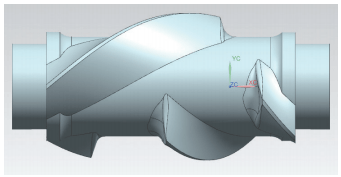
The rotor body of the internal mixer is divided into GN shear type and GE mesh type (see Figure 1 and Figure 2). The shear type is further divided into 4-rib, 6-rib and ZZ2 type. The basic structure is the profiled part in the middle. The profile includes edge top, edge bottom, opposite surface, back surface, side, end surface and pinhole. the process stops, and there are process plans and process holes on the process stops. The surface characteristics of the GN shear type rotor body are more complex than those of the GE mesh type, with larger curvature changes, many fillets of varying diameter, and are composed of small narrow areas.
Figure 1 GN shear type internal mixer rotor body

Figure 2 GE Mesh Type Internal Mixer Rotor Body
03 Machine tool structure
The processing equipment is a MAZAK E670H 6000U machine tool. The structure is shown in Figure 3. It has a total of 7 axes: X, Y, Z, B, C, W and V. It has a five-axis linkage function. The maximum travel of the, the maximum travel of the Z axis is 6170mm, and the middle frame is 350-700mm. Equipped with 24 inch hydraulic chuck (1 inch = 0.0254 m); a large thrust point with a load capacity of up to 7 t; a high-performance, high-torque spindle with a turning spindle power of 45 kW and a milling spindle power of 37 kW; long boring bar system (see Figure 4), using This is a Sandvik Coromant vibration-damped boring bar with a length of 1.8 m, an internal length of 0.5 m and a bore length of 1.3 m.

Figure 3 Structure of the MAZAK machine tool

Figure 4 LBB Long Boring Bar System
Gantry machine tools use double chucks, one active chuck and one driven chuck, which is more convenient in terms of clamping. Figure 5 represents a gantry-type double turntable machine tool.

Figure 5 Double gantry turntable machine tool
04 Preparation of material
Before production and processing, 3D digital models, post-processing, casting blanks and cutting tools must be prepared.
(1) The design uses UG NX 12.0 software for CAD and CAM design of the rotor body.
(2) Programming uses ESPRIT2018 software, using milling module, composite turning and milling module and four-axis composite and turning and milling post-processing.
(3) The material of the blank is cast steel, grade ZG300-560, with a margin of 10~15mm and a process stop length of 150mm for composite turning and milling equipment, the process stop length is 250mm.
(4) Equipment 4 m gantry with double four-axis turntable or MAZAK E670H 4000U and 6000U composite turning and milling machine tools.
(5) Siemens 840D or MAZAK Smooth system.
(6) The inspection uses Geomagic Control software analysis and ZGScan scanning.
(7) Depending on the shape of the workpiece, the tool uses a round blade for profiling processing. The handle system of the tool uses Sentai Inge BT50 or CAPTO 8 interface. The blade is R6mm, which has high strength and low cost. By choosing Octac RPMT1204MOE AP301U blade, the processing cost of cast steel is low and durable. Since the rotor body involves many models, considering the size and stroke of the machine tool, in order to improve the processing efficiency, a rounded disc milling cutter is selected. For GE mesh rotor body, D100mm R6mm or D80mm R6mm disc milling cutter is selected. depending on the size of the model; for GN shear type rotor body, disc mill D63mm R6mm (4 edge comb, length 175mm) and D32mm. R6mm disc cutter (2 edge comb, length 175mm) can meet the needs of all models.
(8) Auxiliary In order to perform spiral cutting without damaging the left and right end faces, offset the end faces by 5 mm. If there is a direct offset alarm, use the extension curve, trim curve, scan, surface trim, and closed surface functions. to create an auxiliary surface.
05 Fang Yi design
5.1 Process route design
The design of the process route for processing the GN shear rotor body is shown in Table 1, including the setting of the processing coordinate system and the safety pin coordinate system, the design of the Special-shaped curved surface processing process route, the design of various reference slots and holes. , and the analysis of the final results verifies.
Table 1: Processing route design for processing GN shear rotor body

5.2 Tightening and correction methods
(1) The clamping method is mainly gantry clamping and auxiliary chuck clamping. The double chuck operation is the simplest; turning and milling are hydraulic main chuck, center chuck, self-centering chuck or single action chuck with a flange installed at the mouth of the shelf after finishing. the frame mouth to ensure concentricity, the central frame Frame support; If the above conditions are not met, you can use the tooling of the main chuck, top and inner sleeve to adjust the inner hole, and use a dial indicator to measure to ensure that the frame ports left and right are coaxial, and then the auxiliary central frame support. The axial circular runout must be less than 0.1 mm. The MAZAK turning and milling clamping is shown in Figure 6.

Figure 6 Clamping diagram for MAZAK turning and milling
(2) The Y axis and Z axis of the tool setting reference point are the rotation center of the self-centering hydraulic chuck. Use the center bit to move to the center point of the long edge to determine the X value and angle A of the rotor. body coordinate system G54; move on to the safety pin. The plotting point determines the value X and angle A of the coordinate system of the safety pin G55 and G56. Since the safety pin is drilled last and the scribe point disappears after the shape is milled, the coordinate. The system must be registered in advance. The reference point for setting the GN400 tool is at the center of the long edge, as shown in Figure 7.

Figure 7 The GN400 tool setting reference point is at the center of the long edge
5.3 CNC process design
(1) Outer circle milling Outer circle milling (see Figure 8) can effectively ensure that the turning and milling marks are unified, and the efficiency of milling is 4 times that of turning. If you are turning the outer circle, mark the line first, then turn the outer circle and end face. After turning the outer circle, the marking point disappears, and you have to notice and then mill the shape.[1]. Since repeated marking will cause data inconsistency, it is easy to cause deviations in the end face and shape of turning. 90% of the area is empty area, so the turning efficiency is low and intermittent turning causes greater losses to the tool and. machine tool.

Figure 8 Outer milling circle
(2) Before attempting to cut the top edge, check whether the reference point is accurate. Try cutting 4 edges and 8 lines with a radial tolerance of 5mm. This process mainly aims to check whether the distribution of the blank margin is uniform. it is not uniform, it can be adjusted the angle of A-axis or C-axis to ensure that the remaining quantity is evenly distributed. The top edge cutting test is shown in Figure 9.

Figure 9 Top edge cutting test
If the reference point of the marking process is incorrectly marked or missed due to individual reasons, if it is incorrectly marked, adjust the rotation axis angle after trial cutting to ensure average machining allowance, if it is missed, take the median value; left and right end faces. Use a center drill to drill a point on the long edge to a depth of 0.2mm. Place one end of the tape measure on this point, parallel to the Y axis, measure the distance between the two. ends of the long edge and take the middle to get the X value and the A value. No need to strip again, this is done by machine.
(3) Processing the root circle of the edge. The root circle should be processed first.[2]can ensure the smooth processing of step 4. Otherwise, step 4 is processed downward and the tool axis faces the center, which will form complete processing during linkage machining. The tool will be easily scrapped due to the phenomenon of. tilting the tool downwards. When changing down milling and reverse milling, Milling, make sure that the tool entry and retraction positions are always in the blank area. Set tool retraction to 0 mm. Retracting the tool in the binding state can easily cause the tool to be scrapped. The root of preclearance is shown in Figure 10.

Figure 10 Pre-cleaning the roots
(4) Edge processing technology requires a casting allowance of 10-15mm, but it may be unevenly distributed. Frequent advance and retraction of the tool should not be used for all treatments. one feeding at a time is fine. The tool can be retracted to achieve high feed speed. It can be processed in one go. The cutting depth ap = 1 mm allows you to obtain both efficiency and quality. During this step, care should be taken to leave a space of 5-10mm between the left and right end faces to avoid damage to the turned end faces. Edge processing is shown in Figure 11.

Figure 11 Edge processing
(5) Rough machining of left and right end half circles and half circles (see Figure 12), using the linked line cutting method. Each processing line is rotated, using a direct connection instead of an arc shape to avoid a center cut. the center of the tool is offset by 50% of the diameter, use side edge processing; the line spacing is 2mm, the side wall and bottom margin are 0.3mm, and the feed speed vf = 4000mm/min.

Figure 12 Rough machining of semicircles at left and right ends
(6) Area rough machining: This area uses four-axis overall linkage machining. The tool axis is perpendicular to the center. The processing depth adopts a constant cutting depth. The processing distance should be controlled at 15mm above the surface. base circle smaller than the semicircle treated in step 5. It is recommended to use 1/4 of the tool diameter to round the fillet. The roughing area is shown in Figure 13.

Figure 13 Area rough machining
(7) Rough machining of the base circle removes the base circle allowance to ensure uniform finishing allowance. The shape being complex, machining with connection and fixed axis is possible.
The casting tolerance of the base circle is 10mm. If you rotate the shelf mouth, the shelf mouth and the base circle will no longer be concentric.[3]there are high points and low points, so taking into account the machining characteristics of the tool, the machining allowance is 15 mm.
If fixed axis machining is used, i.e. the base circle is machined at fixed axis angles, then the machine tool stroke and tool length are taken into account. account, and the ZZ2 and 4 edge rotor bodies are processed into 5 equal parts from GN270. to GN400.
If linked machining is used, the center will push the tool, so the line spacing is set to 50% of the tool diameter and the feed rate is about 70% of the machining with fixed axis. The related rough machining base circle is shown in Figure 14.

Figure 14 Basic Roughing Circle Linked
(8) The root of the finishing edge is cleaned spirally, and the surface quality is good. The margin after rough machining is small and the feed speed vf=5000mm/min. Due to the constant height machining method, it is not appropriate to use averaging and optimization methods for the cutting depth here. The residual height is adopted, the maximum cutting depth is 1mm, and the processing residual height is 0.5mm. The root of the finishing edge is shown in Figure 15.

Figure 15 Finishing the edge root
(9) Finishing the base circle to finish all parts of the circle, using the linked line cutting method. Each processing line is rotated and directly connected. Since a round nose milling cutter is used, the center of the tool has no cutting capability. The tool center is offset by 50% of the diameter to prevent center cutting, the line spacing is 1.5 mm and the feed rate vf=5000 mm/min. Figure 16 shows the finishing base circle portion.

Figure 16 Finishing the base circle portion
(10) Milling reference groove In order to ensure that the CNC milling blank and the subsequent CNC milling high hardness alloy data are unified, level the rotation axis and determine the origin of the groove depth = (outer diameter of frame mouth – inner diameter) /. 5 (mm), depth range 5 ~ 10mm, correction length ≥100mm, slot width 20mm.
(11) Drilling the reference point Since Kobelco and Leis welding robots are used to weld stainless steel and very hard alloy materials in the later process, the robot must use the welding wire on the welding gun to align the reference point on the part. To make sure the origin of the offline programming program is the same as the origin of the robot, they overlap, so use a D10mm center drill to drill a hole in the center of the reference groove with a depth 5mm. This method has fast welding speed and high precision, much higher than the edge search correction method.
(12) Pre-drill the safety pin hole to make it easier to align the safety pin when drilling later. The drilling diameter is 10mm and the depth is 20mm. They are processed together in this process. re-marking after CNC machining in the past. The radial drill continues processing. Milling the reference slot and drilling the reference hole are shown in Figure 17.

Figure 17 Milling the reference slot and drilling the reference hole
(13) The maximum outer circle GN shear type rotor body for precision milling uses a UV curved surface to ensure reasonable distribution of the flow direction of the UV surface. With the simplified processing of the curved surface, the forward tilt angle is 2°. , and tool-side edge processing is maintained around the X axis, limiting simultaneous processing on four axes. Figure 18 shows the outer circle of the finely milled GN shear rotor.

Figure 18 Outer circle of GN shear type rotor for precision milling
Since the GE gill rotor body has a relatively large surface area, it is more suitable to use line cutting. It has fewer moving axes and can ensure higher feed speed. When using UV curved surfaces, you need to use the internal functions of UG or CAM as the training surface, ensure the UV direction is along the X axis, offset the tool center by 50% of the diameter, hold the side edge of the tool. processing along the X axis and limit it to simultaneous processing on four axes. Figure 19 shows the precision milling of the outer circle of the GE mesh rotor.

Figure 19 Precision milling of outer circumference of GE mesh rotor
06Checking the analysis
6.1 Installation and scanning of the part
Since the workpiece is heavy and cannot be rotated manually, tooling must be made and the workpiece is placed on the rotating tooling. The magnets are fixed evenly in the axial and circumferential directions of the processed parts, and the ZGScan scanner is used to. scan parts evenly on Geomagic Control Imaging.
6.2 Digitization and its requirements
The scanned model is compared to the 3D digital model to determine the best fit. The comparison result should be controlled within ±0.2mm. The GK400N-4 rib rotor body is shown in Figure 20, and its 3D comparison results are shown in Figure 21. The average error is ±0.2mm, and the green part is within the tolerance range.

Figure 20 GK400N-4-edge rotor body

Figure 21 3D comparison results of GK400N-4 rib rotor body
07 Combined turning and milling, machining and clamping
7.1 Process shutdown time
Since the gantry type double turntable processing equipment is double clamped, the length of the process stop is designed to be 150mm. MAZAK E670H 4000U or 6000U and other 4m or 6m turning and milling equipment use hydraulic chuck, middle frame and upper structure. The collision distance between the left end surface of the middle frame and the product must be considered and no interference is allowed. The distance to the top should be extended appropriately, 300mm for 4m equipment and 400mm for 6m equipment.
7.2 Fixing flanges and alignment
The composite clamping method by turning and milling is shown in Figure 22. The center is supported, the single-action chuck is equipped with a flange, the center steering shelf mouth is calibrated with a dial indicator and the axial circular runout is controlled within 0.1mm, a center-mounted turning tool is used, rotated 45°; °, and the turning process of cermet turning tool CNMG120404 is used. Stop the aperture to ensure that the surface roughness value Ra is less than 1.6 μm and serves as the central frame position.

Figure 22 Composite clamping method in turning and milling
08Conclusion
1) This process plan has been perfected after 2 years of continuous optimization and 3 years of continuous processing verification. Not only is the processing quality good, there is no need for inspections of prototypes and roller tooling. After 3D scanning, the tolerance is controlled to ±0.2mm. The treatment efficiency is very high and the cost is reduced by 85% compared to before. . The largest GE gill rotor body, the GE1000T rotor body, has a diameter of 1m and a length of 1.3m, and takes only 24 hours to process. The largest GN shear rotor body, GN400-4 rib rotor body, only needs 24 hours. 16 hours processing time and suitable for internal mixer rotor body blanks. High-efficiency production in large quantities can be directly used by internal mixer companies.
2) This process design can realize the processing of a full range of internal mixer rotor bodies, including GE mesh type, GN-4 rib shear type, GN-6 rib shear type , shear type GN-ZZ2 and other rotor bodies with similar structure. The processing basically meets the processing needs of the internal mixer rotor body, and can also be used on four-axis machining centers and composite turning and milling equipment.
3) Regarding other possible related processes, use milling instead of turning the outer circle, datum groove and point design. If the welding surface layer is a high hardness alloy, consider using mechanical processing. This process design can effectively connect CNC milling alloy. Process and is convenient. Origin of welding robot calibration, etc.
Daguang focuses on providing solutions such as precision CNC machining services (3-axis, 4-axis, 5-axis machining), CNC milling, 3D printing and rapid prototyping services.


