Upper gear plate-1; connection part 2, limit groove-2a, clamp groove-2b; lower support box-3; pin positioning block-5, positioning groove-5a; key-7; rotating cylinder body -8; 9; Connection block 10; Positioning pin 11; Fixed cylinder -13, upper vertical groove -13b, first transverse groove -14; cursor-1 6 ; External convex disc – 17; Washer – 18; Second spring – 19; Tapered shank sleeve – 20; Driven gear – 22; Knife inlet – 23a, Oil inlet lever – 23b; -24; third bomb Spring-25; spring washer -26; spring pressure block -27; four-petaled claw -29; -31 bottom bracket central shaft; end pressure cover-34; rear cable gland-35.

The gantry machining center comprises a spindle, a first pull claw, a second pull claw, a coupling part 2 and an upper gear plate 1. The coupling part 2 is provided with at least two slots 2b on its side.
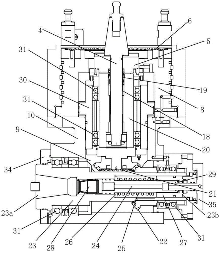
The gantry right angle milling head includes a center axis housing 3, a spindle taper handle 4, a positioning block 5, a lower gear plate 6, a positioning key 7 and a rotating cylinder body 8 located in the central axis housing 3. The anti-drop component 32 is provided on the machine body and is engaged with the clamping groove 2b, the cutter housing 9 and the cutter arranged in rotatably in the cutter housing 9. The lower toothed disk 6 and the upper toothed disk 1 can be meshed. The conical spindle handle 4 passes through the positioning block 5 and is fixedly connected thereto. The upper surface of the positioning block 5 has a positioning groove 5a which cooperates with the lower toothed block 6. positioning key 7. The upper toothed disc 1, the positioning key 7 and the cutter housing 9 are fixedly connected to the rotating cylinder body 8, and the four are in a connection relationship more precisely, this housing also includes a connection block 10, and the connection block 10 is both connected to the cylinder body rotary 8 and to the cutter housing 9. Linkage connection. The central axis housing 3 is provided with a positioning pin 11 for clamping by the first claw. The upper end side of the positioning pin 11 is provided with a tapered surface, so that the first claw can be squeezed from the side to move it. the plate along the conical surface. The spindle The conical handle 4 is provided with a latin 12 for tightening by the second claw.

During the machining operation, the first and second claws of the gantry machining center respectively clamp the bottom bracket 3 and the spindle taper handle 4. At this time, the upper gear plate 1 and the plate The lower gear 6 engages, so that the rotating plate. the cylinder body 8 and the cutter housing 9 cannot rotate, then the main shaft of the gantry machining center drives the spindle taper rod 4 to rotate, thereby realizing that the cutter rotates relative to the cutter housing 9 in the cutter housing 9. When the cutter needs to be transposed, the first claw releases the bottom bracket 3. As shown in Figure 5, the bottom bracket 3 moves down and is supported by the anti-fall element 32 and the card slot 2b. The upper toothed disk 1 and the lower toothed disk 6 are separated. At the same time, as shown in Figure 7, the positioning key 7 is inserted into the positioning groove 5a from top to bottom, so that the positioning key 7 and the positioning disk. the block 5 are locked, so that the conical handle of the spindle 4 rotates. The rotation of the rotating oil cylinder body 8 drives the rotation of the rotating oil cylinder body 8, and the rotation of the rotating oil cylinder body 8 causes the rotation of the cutter housing 9, thereby achieving the circumferential rotation of the cutter for a certain angle. After rotating at a certain angle, the rotating oil cylinder body 8 rises, and the upper gear plate 1 and the lower gear plate 1 move upward. The toothed disc 6 is reengaged, as shown in Figure 6, the. the positioning key 7 is separated from the positioning groove 5a, the spindle taper shank 4 rotates to drive the cutter to rotate, and the processing operation is restarted. It can automatically adjust the angle of the cutter, making it more efficient and more convenient to use.
The fall arrest assembly 32 includes a fixed cylinder 13, a first spring 14, an active corner pin 15 and a passive slider 16. The fixed cylinder 13 is provided with an upper vertical groove 13a which penetrates from top to bottom, a lower vertical groove 13b and a transverse groove 13c which penetrates transversely into the upper vertical groove 13a. The upper end of the active bent corner pin 15 passes through the lower vertical groove 13b and the upper vertical groove 13a in sequence, and the active bent corner pin 15 is provided with an outer convex disk 17. The first spring 14 is fitted onto the active angular corner in the lower vertical groove 13b. The lower end of the first spring 14 abuts the outer convex disk 17 on the pin 15. The passive slider 16 passes through the transverse groove 13c and forms a corner fit with the active corner pin 15, it is that is, the up and down movement of the active corner pin 15 can cause the passive slider 16 to move left and right. The passive slider 16 is provided with a projection 33 which cooperates with the card slot 2b. There is a distance H between the projection 33 and the card slot 2b in the vertical direction. The mating part 2 is provided with a vertically extending limit groove 2a, which is connected to the card groove 2b. When the anti-drop component 32 is installed, the active corner pin 15 moves upward due to hydraulic pressure, causing the passive slider 16 to slide into the transverse groove 13c, and then insert the fixed cylinder 13 into the limiting groove 2a, and slide until the boss 33 faces the blocking groove 2b. At this time, the hydraulic pressure is canceled. , the active corner pin 15 moves downward under the action of elastic force, causing the passive slider 16 to move in the slot 2b, so that the bumps 33 are inserted into the slot 2b to form a lock mutual, thus supporting the anti-fall component. 32, thus supporting the central axis housing 3 will also fall when the first traction claw loosens the locating pin 11, and at the same time it will prevent falling.

It is assumed that the upper toothed disk 1 and the lower toothed disk 6 must move at least a distance L from meshing to complete separation, and that the distance H is not less than the distance L. In this way, when the cutter housing 9 is to be indexed, it can be ensured that the bottom bracket 3 falls far enough to separate the upper toothed disk 1 and the lower toothed disk 6, without thereby hindering the angle of rotation of the bottom bracket 3.
The tapered spindle handle 4 includes a cone and a cylinder. A washer 18 and a second spring 19 are provided on the cylinder. The two ends of the second spring 19 resist the positioning block 5 and the washer 18 respectively. In this way, when the pin is sleeved with the cone, even if there is a slight deviation, under the buffering effect of the spring and the guiding of the cone, the rigid impact can be reduced during the sleeve assembly process and lifespan. equipment can be expanded.
The spindle taper shank 4 is also provided with a taper shank sleeve 20 outside, and the taper shank sleeve 20 is connected to a drive gear 21. The cutter housing 9 also includes a central shaft of cutter 23 and a slave shaft in a fixed manner. connected to the central shaft of the cutter 23. The driving gear 22, the driving gear 21 and the driven gear 22 mesh, and the cutter is fixed in the central shaft of the cutter 23. The two ends of the housing cutter spindle 9 restricts the cutter spindle 23 into the cutter housing 9 through the front end pressure cover 34 and the rear end pressure cover 35. The spindle drives the spindle taper shank 4 to rotate, and the spindle taper 4 drives the central shaft of the cutter 23 to rotate through the mesh transmission relationship between the driving gear 21 and the driven gear 22, realizing thus the rotation of the cutter.
The central cutter shaft 23 is provided with a pull rod 24, a third spring 25, a spring washer 26, a spring pressure block 27 and a four-petal claw 28. The spring pressure block 27 and the four-petal claw 28 are respectively fixed at both ends of the pull rod 24. The third spring 25 is fitted on the pull rod 24 and the two ends resist the spring washer 26 and the spring pressure block respectively. 27. The cutter spindle 23 is located on the pull rod 24. The opposite end of the four-petal claw 28 is provided with a knife inlet 23a, and the opposite end of the spring pressure block 27 is provided an oil inlet 23b. Therefore, when hydraulic oil enters the oil inlet 23b, the spring pressure block 27 is pushed to move toward the tool inlet 23a. While tightening the spring, the pull rod 24 and the four-petal claws 28 move synchronously, so that the four petals. -the petal claws 28 open, and the cutter can insert the four-petal claw 28, and then remove the hydraulic oil, the spring pressure block 27 moves in the reverse direction under the action of elastic force, the pull rod 24 and the four-petal claw 28 also move in the opposite direction, so that the four-petal claw 28 closes and grips the cutter. It should be noted that an oil seal 29 is provided on the tie rod 24 to prevent hydraulic oil from entering the tie rod 24.
The outer sleeve of the tapered rod sleeve 20 is equipped with a central axis central shaft 30. The central axis central shaft 30 is fixedly connected to the rotating oil cylinder body 8. Bearings 31 are provided between the shafts 23 so that the central axis core shaft 30 rotates relative to the taper shank sleeve 20 and the central cutter shaft 23 rotates relative to the cutter housing the cutter 9 more fluidly.

Daguang focuses on providing solutions such as precision CNC machining services (3-axis, 4-axis, 5-axis machining), CNC milling, 3D printing and rapid prototyping services.


