STL files are a standard format for 3D objects, including 3D printing. Its name means “stereolithography” and is sometimes also called “standard tessellation language” and “standard triangulation language”. This type of file represents objects by tessellation, which means creating a mesh of small triangles.
On the other hand,STEP stands for “Standard for Product Model Data Exchange” and is a commonly used CAD file format for 3D models. As the name suggests, STEP files can be transferred from one CAD program to another without any intermediate conversion steps.
The main difference between these two file types is that sinceThe STEP format is specifically designed for CAD editing purposes and is therefore generally easier to edit. Therefore, sometimes it is useful to convert a 3D model saved in STL format to a STEP file. In this article, we will introduce two programs that can be used to convert STL to STEP.

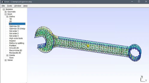
picture1:Grid work is useful for many applications (source:FEATools Multiphysics)
If you download files from an online repository, unless they come fromDesign specific websites like GrabCAD, otherwise the most common format is STL. It’s okay if you plan to print the model immediately or edit it in a program like Blender. However, if you need to use parametric modeling to modify the model, for example adjusting the mechanism of an automaton toy downloaded from Thingiverse, then the STL file is not the best way to modify the model, and it may not be possible at all.
But why? The answer depends on the nature of the document. For ease of understanding, let’s compare it with2D images for comparison. STL files can be compared to raster files (such as JPG), which are composed of pixels with specific colors and positions to make up an image. Raster images are suitable for display purposes, but increasing the size of the image only increases the pixel size, making it look grainy. STEP files, on the other hand, are more similar to vector files such as SVG. Vector files are a set of mathematical properties that make up an image, and it is much easier to edit such files without losing quality and keeping everything in the right proportions.

picture2:STL is mesh, while STEP is solid (Source: Lauren Fuentes via All3DP; Model: thaccactusgirl via Thingiverse)
STEP files offer similar benefits. Not only do they store external geometry like mesh files, but they can also differentiate between solid objects, hollow objects, and surface objects such as leaves. Additionally, STEP files can store information about the object’s material (e.g. steel), constraints (e.g. keeping faces parallel), thickness, dimensions, etc. If you create a solid aluminum ball with a diameter of 5 mm as a STEP file in SolidWorks and then open it in AutoCAD, the new program still knows all the data about the ball.
This is also why the conversion toSTEP files are not as simple as converting STL to OBJ, and that’s why we haven’t recommended a simple online conversion tool. STEP files are inherently different from STL files: the former are solid objects with parameters, while the latter are essentially meshes, so you must first modify the existing mesh to make it a solid. This process is explained in the next section and fortunately, with the right software, it is very simple.
solution1:Autodesk Merge

picture3:Put firstSTL inserted into Fusion to convert it to STEP (Source: All3DP; Model: thaccactusgirl via Thingiverse)
WillAn easy way to convert STL files to STEP files is to use Autodesk Fusion. Since an STL file is basically a mesh, it’s important to note that Fusion supports three different methods of processing meshes, but it’s easiest to plug in just one. In the latest version, Fusion also includes some mesh operations, which are recorded in the operations timeline.
To follow the first method, you need to go to the design workspace, which is openThe default workspace for Fusion.
stage1: Insert a grid:
1、Go to“Insert > Insert Grid”.
2、Select the file to insert. Although this tutorial is intendedSTL, but it should be noted that Fusion can also import meshes in OBJ and 3MF file formats.
3、Once the grid is loaded, you mustSet some options in the “Insert Grid” menu.
Unit type: You can set the units to millimeters, centimeters, meters, inches or feet.
Reverse direction: This feature is useful if your model is inserted the wrong way round, although this is usually not the case.
Location: You can choose to center the model at the origin or have the bottom touch a horizontal surface.
digital input: This field allows you to define the position of the model more precisely.
stage2: Convert mesh to solid

picture4:Then convert the mesh to solids (source:All3DP; model: thaccactusgirl via Thingiverse)
1、To convert the mesh to solids, still in the design workspace, go toGrid tab (pink) and open the Edit menu for the full set of options.
2、choose“Convert mesh”. This will open another menu where you need to select some options.
main body: You can select the subject in the browser or directly in the window.
function: There are two basic options, settings and features. Settings save actions to the timeline and allow you to directly edit existing relationships resulting from the transformation. Basic functionality does not save relationships between parameters and is not saved in the timeline, but you can still perform operations on the obtained objects.
method: There are two options, faceted and prismatic. The facets areFusion has always been the original approach, which takes the original mesh and transforms it into a solid. Prismatic is a newer option designed to merge adjacent faces of a mesh to form a single face of a solid. We recommend using the prismatic method for best results as the object will have the geometry of the STEP file and will be easier to work with. However, this option is not available with the free personal use version of Fusion.
3、If your program can’t decide which faces to merge, you canIn the “Prepare” menu, use the “Generate Quilt” tool before converting the mesh.
stage3: Save as STEP

picture5:save asAs easy as 1-2-3 (Source: All3DP; Model: thaccactusgirl via Thingiverse)
After converting the file to solids, all that remains is to export it as aSTEP file. The resulting file is a solid object that you can modify using operations and functions in any parametric modeling software.
1. Go to the File menu in the upper left corner and select Export.
2、Select the file name and selectSTEP as type.
3、click“Export” button.
that’s all! Remember that exporting will save the file to your computer, while using“Save as” will save it to Fusion’s cloud storage.
solution#2: Free CAD

picture6:existConverting STL files to STEP files in FreeCAD is very quick and easy (Source: All3DP)
WillA free alternative for converting STL files to STEP files is FreeCAD, a downloadable CAD program. Even if you’ve never used FreeCAD before, you can download it and start converting files in minutes.
FreeCAD is available for Windows, Mac and Linux, so you can use it with confidence. At the time of writing, we are using FreeCAD version 0.21.2. After downloading the program, open it and follow this workflow:
1、Select from the top menu“File” then “Open” and select your STL file from your computer.
2、If not enabled by defaultCombined View panel, make sure it is visible. To display this view, select View from the top menu, then select Panels from the drop-down menu, then select Combo View. The combined display panel displays your file name with a green icon next to it.
3、You must ensure thatFiles are processed in the Parts workbench, which has a unique menu bar compared to other workbenches. To select the Parts workbench, go to the topmost menu and click View, then select Workbench, then Parts.
4、Click your file name in the combined view to select it. Then from the top menu select“Part” then “Create a shape from a mesh”. Note that this option does not appear in the Parts menu unless you select the part name in the combined view.
5、WhenWhen the “Mesh Shape” box appears, simply click “OK”.

picture7、STL file converted to mesh, then converted to solid file, then exported to a STEP file (Source: All3DP)
6、Now in the combo display area, the originalThere should be a new grid file named “filename 001” (or something similar) under the STL file. Delete the original STL file since you no longer need it by selecting it, right-clicking, and selecting Delete.
7、Select your new grid file in the combined view (“filename 001”). Then click “Parts” in the top menu and scroll down to “Convert to Solid”.
8、Now in the combined viewThere will be a “Solid” file under the “Mesh” file. You can now delete the grid file.

picture8:Make sure to export the file as“STEP with Color” instead of “Save As” (Source: All3DP)
9、You’re not done yet. Now you need to change the appearance. Select your feature file in the combined view and right-click it. From the menu that appears, select“Appearance”. This will open a new view in the Combined View under the Tasks tab.
10、In the Appearance view, underChoose a color from Shape Color, preferably a bright color like orange. Don’t change anything else in this Appearance task menu, then click the Close button in this menu area. You should now return to your usual view of the combined view.
Notice: It is not absolutely necessary to paint the solid model. This step is often used to improve the visual distinction of transformed geometry becauseMesh models in STL files generally do not retain any color or material properties. Coloring the solid model helps distinguish the solid from the original mesh, which is particularly useful when comparing and validating the converted solid model with the mesh. Also useful when working with assemblies.
11、Similarly, after selecting the feature file in the combined view, go to the top menu and click“File>Export”. When the export file dialog box appears, name the file, choose a location to save to, and select “Colorful STEP” from the File type drop-down menu. The STEP dialog box will appear. The units exported here by STEP should default to millimeters (change only if necessary). If it is not already selected, select the first option: “Write curve in surface parameter space”. The schema should default to “AP214 International Standard”. Change only when appropriate.
12、click“Of course”.
Please note thatFreeCAD does not have an option to merge adjacent mesh elements like Fusion does, so the process is similar to using the Faceted option in that program. The mesh becomes a solid, but its surface is subdivided. That is, you can still perform parameter operations on new entities.
It should be noted that the choice“Save as” instead of “Export” can cause problems. In this case, the file can only be saved as a FreeCAD document, which somewhat defeats the purpose of the STEP conversion, unless you plan to continue modeling only in FreeCAD.
Daguang focuses on providing solutions such as precision CNC machining services (3-axis, 4-axis, 5-axis machining), CNC milling, 3D printing and rapid prototyping services.


