In metal additive manufacturing (AM), adding and removing media has always been a big problem. direct laser sintering of metals (DMLS) For example, a support structure must be predefined for the model before printing to avoid warping caused by thermal stress and to remove heat from the weld pool. These brackets are part of the design and manufactured as a whole. After construction, the support structure was dismantled and scrapped. Without support, it is difficult to print below a certain tilt angle (usually45°) of the suspended structure, which often limits the metal3DUser choice of printing system, also for many devicesOEMand additive manufacturing software publishers pose big challenges

Recently, according to Mohou.com, in order to solve the above problems,E0SbusinessAdditive spiritsexperts have now developed a variety of process optimization techniques to produce support-free structures 3DPrint parts such as stator rings, housings, turbine pumps, fuel tanks, heat exchangers, valves and impellers, of which closed impellers are one of the most typical cases. Through optimized design software and parameter packages,E0SAllows users to print cantilevers and bridges at lower angles (sometimes even zero angles), requiring much less or no support.


Supportless additive manufacturing also saves a lot of time in the post-processing phase, as there is no need to remove additional supports. In the case of manual removal, this also frees up staff time and energy for other tasks. Manufacturing parts without support structures also reduces material waste because nothing is thrown away and every aspect of the part design and support is required. However, it’s not a simple process, and software design experts and manufacturers have struggled with the challenges of unsupported design for years.
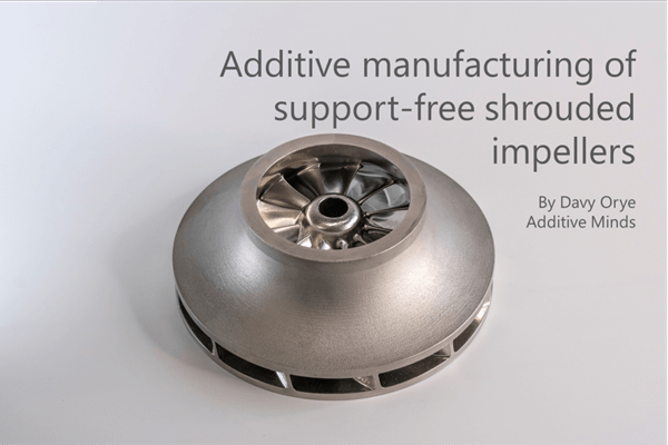
In this article, we mainly showEOSExperts on how to build wheels using the supportless method. Enclosed or shrouded turbines are used in many industries and vary widely in size, shape, materials and performance requirements. Enclosed impellers are often exposed to various extreme conditions, such as high rotational speeds, highly corrosive fluids, and mechanical loads caused by extreme temperatures. Examples include turbopump applications in space rockets, compression systems in micro gas turbines, and seawater pumps in oil and gas applications.
traditional metal3DSupporting design requirements when printing
Designed with support 3D Prints have always been manufactured additively (AM) standard method. The number, size and location of supports are determined by various factors:
Residual stresses from the printing process can cause 3D Model deformation. Supports can be added to physically prevent this deformation;
Collector Interruption Intermediate constructions that affect the workpiece can cause it to vibrate or cause damage, leading to job failure. Supports are used to protect the parts from any impact from the collector;
Heat transfer through media Allows parts to cool and form more quickly and successfully during the building process.


To ensure3DFor your printer to be built and successfully produce parts, you need to consider various factors that influence your media design, including:
room orientation Determine the level of support the part needs. Generally, if the part is oriented so that more surface area is outside the build plate, more support will be needed to compensate for the above factors.
45 Overhangs of 10 degrees or less are generally considered to require a support structure.
Channels and holes can become distorted without support, depending on their size and if they are incorrectly oriented.


Model design
With the right expertise and creative problem-solving skills,EOS The team successfully developed new ways to design and build models, breaking the preconceived notion that supports should be added for low inclinations and achieving exceptional results. This article is used to demonstrate unsupported structures and DMLS The process function wheel consists of EOS additive spirits Designed with a diameter of 150 mm with 12 overhang angle as low as10 degree of leaves.

△The design of the wheel. source:EOS
Direction of inclination of components and support structure
Turbines are often printed in a tilted orientation to avoid internal supports as they are difficult to remove. However, this orientation often results in longer build times, uneven surface quality, and compromised part roundness. Planar orientation offers several benefits, such as shorter build times, better roundness and accuracy, and more uniform surface quality throughout the part. However, low overhangs often require a lot of support. for the current DMLS process, requiring a support angle less than 35° Large overhang. Supports are required to dissipate heat from the weld pool to compensate for overlapping forces and internal stresses in the part.

△Conventional orientation and resulting support structure (right), inclined hull (left). source:EOS
Unsupported design optimization
EOSBy leveraging advanced template design techniques, the need to add internal supports is significantly reduced. Optimizing the design of the additive manufacturing process is also another important aspect related to printing success. Although internal bracing can be avoided primarily through the use of suitable exposure strategies, external support structures are often still necessary.
In the case of this article’s turbine, instead of using solid infill, the bottom of the part was modified using self-supporting hoops and thin walls to ensure a solid connection to the platform and prevent distortion during the construction process. This allows less material to be used than with conventional supports while providing high strength and improved machinability. The outer diameter of the wheel is closed to provide greater rigidity to the part once constructed and to avoid loss of geometric precision at the exit edge. For this turbine, the advanced design reduces 15% The material features both processing optimization and a self-supporting structure without internal support.

△Traditionsagainst Built without supports. source:EOS
Process optimization
The turbine uses what is called high energy DownSkin Method (the type of exposure used to construct overhanging surfaces) construct. Essentially, this method increases the power of the laser while adjusting other DownSkin parameters to increase DownSkin Energy density entry for the exhibition. This creates a larger but more stable melt pool, especially when building overhangs on loose powder. This method has been used successfully for many materials frequently used in wheel manufacturing (e.g. Ti64、316L、AlSi10Mg、En718 wait).
Therefore, it is guaranteed that all critical angles can benefit from this optimized setting. Unlike other unsupported technologies, high energy technologiesDownSkin The approach does not sacrifice construction speed and therefore does not sacrifice the business case to avoid shoring.
Without any countermeasures, due to the deep, high energy fusion pool DownSkin the method will result DownSkin in the area z The size of the orientation piece is too large. Parts can be adjusted to the appropriate size through post-processing or by adjusting the design.DownSkin It is also relatively rough, but the roughness is uniform, which facilitates mass surface treatment techniques such as abrasive flow machining. There are also virtually no pores (see photo below), pores are limited to DownSkin. Therefore, the overall mechanical properties are not affected and you can always rely on EOS Developed with high quality Filling Craftsmanship. Therefore, secondary processes such as hot isostatic pressing are also not necessary to achieve adequate mechanical properties.

△High energy transversalDownSkin exposure. source:EOS
The print quality of the components can be seen in the image below:

△The image highlights the high energy DownSkin methodological DownSkin quality. source:EOS
Post-processing (abrasive flow machining,AM Metals)
Abrasive flow machining is a common surface finishing technique used for flow-related applications and internal geometries. The abrasive material is pushed through the workpiece held in a holder. Abrasive particles in the media grind and polish the surface along the flow path. To prepare for interior surface finishing, the closed outer diameter must be machined to an open diameter, with the diameter and height of the part adjusted to the AFM Handcrafted lighting. After pre-machining, the workpiece is clamped and the abrasive is pushed through the workpiece using a clamp. exist AFMAfter the process, the wheel is machined to its final size.
Treatment with abrasive flux (AFM) The final part after treatment

△AFM View down from the rear turbine. source:EOS

△AFM Detailed view of the upper surface of the rear wheel. source:EOS

△AFM Detail of the lower surface of the rear wheel. source:EOS

△The lower surface of the wheel after treatment. source:EOS
Source: Antarctic Bear
Daguang focuses on providing solutions such as precision CNC machining services (3-axis, 4-axis, 5-axis machining), CNC milling, 3D printing and rapid prototyping services.


